 مستشعرات درجة حرارة الألياف البصرية INNO ,أنظمة مراقبة درجة الحرارة.
- Overheating at switchgear contacts الأسباب 60-70% of electrical distribution failures – مراقبة درجة حرارة الألياف الضوئية الفلورسنت provides intrinsically safe, real-time condition monitoring solutions
- مستشعرات درجة حرارة الألياف البصرية offer complete electrical isolation and immunity to electromagnetic interference, withstanding voltages exceeding 100كيلو فولت while maintaining direct contact with energized conductors
- Industry-leading measurement accuracy of ±1 درجة مئوية with response time under 1 ثانية significantly outperforms wireless temperature monitoring systems (±2-3 درجة مئوية, 3-5 الرد الثاني)
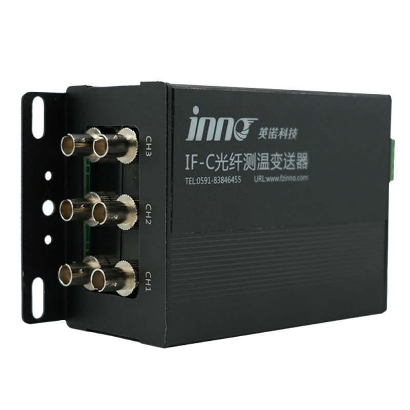
- Scalable architecture supporting 1-64 monitoring channels per demodulator unit, مناسبة ل 10kV to 500kV switchgear applications across substations, مراكز البيانات, والمرافق الصناعية
- 25+ years operational lifespan with zero battery replacement requirements and fiber transmission distances up to 80 امتار enable true maintenance-free long-term deployment
- Complete immunity to RF interference and strong electric fields delivers reliability far superior to مراقبة درجة الحرارة اللاسلكية and infrared thermography alternatives
- مدمج الاتصالات RS485 مودبوس, عتبات إنذار قابلة للتخصيص, تحليل اتجاه درجة الحرارة, وقدرات الصيانة التنبؤية من خلال برامج المراقبة المركزية
- ثبت الامتثال للمعايير الدولية بما في ذلك IEC 62271 و دي إل/تي 1500-2016, مع عمليات النشر الناجحة في المحطات الفرعية, أنظمة المعدل الصناعي, والبنية التحتية الحيوية لتوزيع الطاقة على مستوى العالم
جدول المحتويات
- لماذا ترتفع درجة حرارة خزانات المفاتيح الكهربائية وما هي المكونات الأكثر عرضة للخطر؟?
- ما هي المخاطر والخسائر الاقتصادية الناتجة عن ارتفاع درجة حرارة المفاتيح الكهربائية?
- ما هي القيود والمخاطر المتعلقة بالسلامة الموجودة في الطرق التقليدية لمراقبة درجة الحرارة؟?
- كيف تعمل أنظمة مراقبة درجة حرارة الألياف الضوئية الفلورية?
- ما هي المزايا الأساسية لأجهزة استشعار درجة حرارة الألياف الضوئية مقارنة بالأنظمة اللاسلكية?
- ما هي المواصفات الفنية التي تحدد مجسات درجة حرارة الألياف الضوئية الفلورية؟?
- How Are Temperature Monitoring Points Configured in High Voltage Switchgear?
- What Are the Critical Monitoring Locations in Medium Voltage Switchgear (10كيلو فولت-35 كيلو فولت)?
- Why Do Rectifier Cabinets Require Specialized Temperature Monitoring?
- What Additional Parameters Should Be Monitored Beyond Temperature?
- How Is Multi-Parameter Condition Monitoring System Architecture Designed?
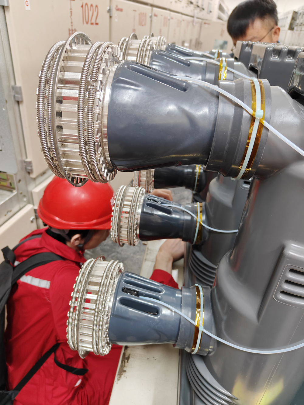
- What Installation Methods Apply to Live Switchgear Equipment?
- Global Customer Application Case Studies
- الأسئلة المتداولة (الأسئلة المتداولة)
1. لماذا ترتفع درجة حرارة خزانات المفاتيح الكهربائية وما هي المكونات الأكثر عرضة للخطر؟?

Switchgear overheating originates primarily from increased contact resistance at current-carrying connections. The four most critical heat-generating locations include:
اتصالات قواطع دوائر (Moving and Fixed)
Contact resistance increases due to surface oxidation, ارتداء الميكانيكية, and erosion from arc discharge. في قواطع دوائر الفراغ, contact degradation accelerates after 5,000-10,000 عمليات التبديل. قواطع الدائرة SF6 experience similar degradation, with contact resistance potentially increasing 200-300% over equipment lifespan.
مفاصل بسبار ونقاط الاتصال
Bolted busbar connections loosen from thermal cycling, اهتزاز, and inadequate torque application during installation. Studies indicate that 40-60% ل مفاتيح الجهد المتوسط installations exhibit undertorqued connections. A 20% reduction in contact pressure can double joint resistance.
Disconnect Switch Contact Points
Knife-blade type isolator switches are particularly vulnerable. Oxidation layers form on contact surfaces, especially in humid environments. Spring pressure degradation over 10-15 years reduces contact force by 30-50%, exponentially increasing resistance.
Cable Terminations and Lugs
Improper crimping techniques, dissimilar metal connections (aluminum-copper), and inadequate surface preparation create high-resistance joints. Thermal expansion mismatch between conductors and termination hardware progressively loosens connections.
Thermal Runaway Mechanism
تؤدي المقاومة المتزايدة إلى توليد الحرارة بعد فقد I²R. تزيد درجة الحرارة المرتفعة من المقاومة (معامل درجة الحرارة الإيجابية), خلق حلقة ردود فعل مدمرة. بدون تدخل, تؤدي هذه السلسلة إلى فشل العزل وتلف المعدات بشكل كارثي.
2. ما هي المخاطر والخسائر الاقتصادية الناتجة عن ارتفاع درجة حرارة المفاتيح الكهربائية?
خلل في درجات الحرارة في المفاتيح الكهربائية ذات الجهد العالي بدء تقدم يمكن التنبؤ به لتدهور المعدات:
40-60نطاق درجة الحرارة درجة مئوية
تبدأ مقاومة الاتصال بزيادة قابلة للقياس. تتسارع معدلات الأكسدة على أسطح النحاس والألومنيوم. وهذا يمثل نافذة التدخل الأمثل حيث مراقبة درجة حرارة الألياف الضوئية تمكن الصيانة الوقائية قبل حدوث ضرر دائم.
60-80نطاق درجة الحرارة درجة مئوية
تتسارع شيخوخة المواد العازلة بشكل كبير – باتباع معادلة أرهينيوس, كل ارتفاع بمقدار 10 درجات مئوية يضاعف معدل التحلل. تفقد مركبات راتنجات الايبوكسي قوتها الميكانيكية. عزل الكابلات (XLPE, إي بي آر) يبدأ الشيخوخة المبكرة, تقليل العمر المتوقع لمدة 30 عامًا إلى 15-20 اعوام.
80-105نطاق درجة الحرارة درجة مئوية
قد تتعثر أنظمة حماية المعدات, causing unplanned outages. In industrial facilities, sudden power loss to critical processes results in production losses of $10,000-$100,000 كل ساعة. Data centers experience potential equipment damage and service interruptions.
Above 105°C
Dielectric breakdown probability increases dramatically. Thermoplastic components deform. Silver-plated contacts exhibit rapid tarnishing. Risk of fire ignition, انفجار (in oil-filled equipment), and total equipment destruction.
Documented Failure Statistics
Industry data from utility companies and industrial facilities reveals that contact overheating accounts for 65-75% ل switchgear failures. Equipment without continuous monitoring experiences failure rates 8-12 times higher than monitored installations. Annual economic losses from overheating-related failures exceed $500 million globally, with indirect costs (توقف الإنتاج, emergency repair mobilization) representing 5-10× direct replacement costs.
3. ما هي القيود والمخاطر المتعلقة بالسلامة الموجودة في الطرق التقليدية لمراقبة درجة الحرارة؟?
Infrared Thermography and Thermal Imaging
المزايا: قياس عدم الاتصال, visual thermal maps, rapid area scanning
Critical Limitations:
- Cannot penetrate metal enclosures – requires equipment de-energization and door opening (خطر السلامة, arc flash risk)
- Emissivity variations cause ±5-8°C measurement errors on oxidized, painted, or polished surfaces
- الفحص الدوري فقط (عادة ربع سنوية) – cannot detect rapid thermal events
- المفاتيح الكهربائية المعزولة بالغاز SF6 and sealed compartments completely inaccessible
- Labor-intensive – requires trained thermographers, scheduling conflicts reduce coverage
Wireless Temperature Monitoring Systems
المزايا: لا الأسلاك المطلوبة, relatively simple installation
Significant Drawbacks:
- Battery lifespan 3-5 years requires periodic replacement on energized equipment (high-risk work)
- Electromagnetic interference in بيئات الجهد العالي الأسباب 5-15% data packet loss
- Measurement accuracy ±2-3°C insufficient for early fault detection
- RF signal attenuation through metal enclosures reduces reliability
- تفشل أجهزة الاستشعار التي تعمل بالتصوير المقطعي المحوسب أثناء ظروف الحمل المنخفض (تحت 30% التصنيف الحالي)
- يؤدي انحراف درجة الحرارة مع مرور الوقت إلى انخفاض دقة المعايرة
الحرارية وRTD (PT100) الأنظمة
المزايا: التكنولوجيا الناضجة, تكلفة استشعار منخفضة
المشاكل الأساسية:
- الموصلات المعدنية تشكل مخاطر السلامة الكهربائية في تطبيقات الجهد العالي
- عرضة للتداخل الكهرومغناطيسي – إشارة الفساد في بيئات المفاتيح الكهربائية
- تنسيق العزل المعقد مطلوب ل >10تطبيقات كيلو فولت
- يؤدي تركيب الأسلاك على نطاق واسع إلى زيادة تكاليف العمالة ونقاط الفشل
4. كيف أنظمة مراقبة درجة حرارة الألياف الضوئية الفلورية عمل?

أجهزة استشعار درجة حرارة الألياف الضوئية الفلورية استخدم مجسات بلورية نادرة مخدرة بالأرض والتي تنبعث منها مضان عند إضاءتها بضوء الإثارة. الوقت تسوس مضان يسلك دقيقة, علاقة متكررة مع درجة الحرارة المطلقة – تشكيل مبدأ القياس.
عملية القياس
- مرحلة الإثارة: ينقل مصدر LED أو الليزر الضوء الأزرق/الأشعة فوق البنفسجية عبر الألياف الضوئية للتحقيق
- جيل الإسفار: الفوسفورات الأرضية النادرة (typically europium or dysprosium compounds) absorb photons and emit red/infrared fluorescence
- Decay Analysis: After excitation ceases, fluorescence intensity decays exponentially with temperature-dependent time constant
- حساب درجة الحرارة: Demodulator measures decay time with nanosecond resolution, applies calibration curves to determine temperature
خصائص السلامة الجوهرية
This optical measurement technique provides inherent advantages for مراقبة حالة المفاتيح الكهربائية:
- عزل كهربائي كامل: Glass fiber contains zero conductive materials – no electrical connection between sensor and measurement electronics
- حصانة EMI: Light signals unaffected by electric fields, المجالات المغناطيسية, or radio frequency interference
- No Metal Components: Ceramic or polymer-encapsulated probes eliminate grounding concerns and voltage stress
- Unidirectional Transmission: Optical signal path prevents external interference coupling
5. ما هي المزايا الأساسية لأجهزة استشعار درجة حرارة الألياف الضوئية مقارنة بالأنظمة اللاسلكية?

Measurement Performance Superiority
دقة: أجهزة استشعار الألياف الضوئية الفلورسنت تحقيق دقة ±1 درجة مئوية عبر نطاق -40 درجة مئوية إلى +260 درجة مئوية, مقابل ±2-3 درجة مئوية للأنظمة اللاسلكية. يتيح هذا التحسين بمقدار 2-3× اكتشاف الأخطاء الأولية 6-12 قبل أشهر.
وقت الاستجابة: تلتقط الاستجابة التي تبلغ أقل من ثانية واحدة التحولات الحرارية السريعة أثناء عمليات التبديل. تظهر أجهزة الاستشعار اللاسلكية عادة 3-5 التأخير الثاني, في عداد المفقودين الأحداث الحرارية الحرجة.
الاستقرار على المدى الطويل: مبدأ القياس البصري محصن ضد انحراف المعايرة. يظهر الاختبار المستقل <0.5درجة مئوية الانحراف على مدى فترات 10 سنوات. تظهر أجهزة الاستشعار اللاسلكية انجرافًا بمقدار 1-2 درجة مئوية في الداخل 2-3 اعوام.
الموثوقية والتوافر
متطلبات الصيانة: تعمل أنظمة الألياف الضوئية بدون صيانة 25+ سنوات بدون مكونات مستهلكة. تتطلب الأنظمة اللاسلكية استبدال البطارية كل يوم 3-5 اعوام – عبئا كبيرا على السلامة والخدمات اللوجستية في المنشآت ذات الجهد العالي.
سلامة البيانات: يسلم النقل البصري 99.99%+ توفر البيانات. تجربة الأنظمة اللاسلكية 5-15% فقدان الحزمة في البيئات الصاخبة كهربائيا, creating monitoring blind spots during critical events.
Environmental Resilience: Fiber optic probes function reliably in temperature extremes, رطوبة عالية, التكثيف, and corrosive atmospheres. Wireless electronics vulnerable to moisture ingress and thermal stress.
السلامة والامتثال
تحمل الجهد: Tested to >100kV voltage, مستشعرات درجة حرارة الألياف البصرية mount directly on energized 500kV components. Wireless sensors limited to lower voltage levels due to electronic components.
سلامة قوس فلاش: Complete electrical isolation eliminates potential ignition sources. Critical for hazardous area installations and explosive atmosphere environments.
التكلفة الإجمالية للملكية
While fiber optic systems exhibit higher initial equipment costs ($800-1,200 per channel vs. $200-400 for wireless), total 20-year ownership costs favor fiber optics:
- Zero battery replacement labor and materials
- No outage windows required for sensor maintenance
- Lower false alarm rates reduce operations costs
- Extended equipment life through earlier fault detection
Industry analysis demonstrates fiber optic total cost of ownership approximately 1/3 ل 1/5 of wireless alternatives over equipment lifespan.
6. What Technical Specifications Define مجسات درجة حرارة الألياف الضوئية الفلورية?
كقائد fiber optic temperature monitoring system manufacturer, we provide detailed specifications for informed system selection:
نطاق قياس درجة الحرارة
-40درجة مئوية إلى +260 درجة مئوية continuous operation covers all المفاتيح الكهربائية applications including extreme arctic installations and high-temperature industrial processes. Custom ranges available for specialized requirements.
دقة القياس
±1 درجة مئوية الدقة المطلقة maintained across full measurement range. Repeatability ±0.5°C enables reliable trend analysis and early anomaly detection.
وقت الاستجابة
تحت 1 ثانية (T90) from temperature step change to 90% of final reading. Critical for capturing transient thermal events during circuit breaker operations, fault currents, and load switching.
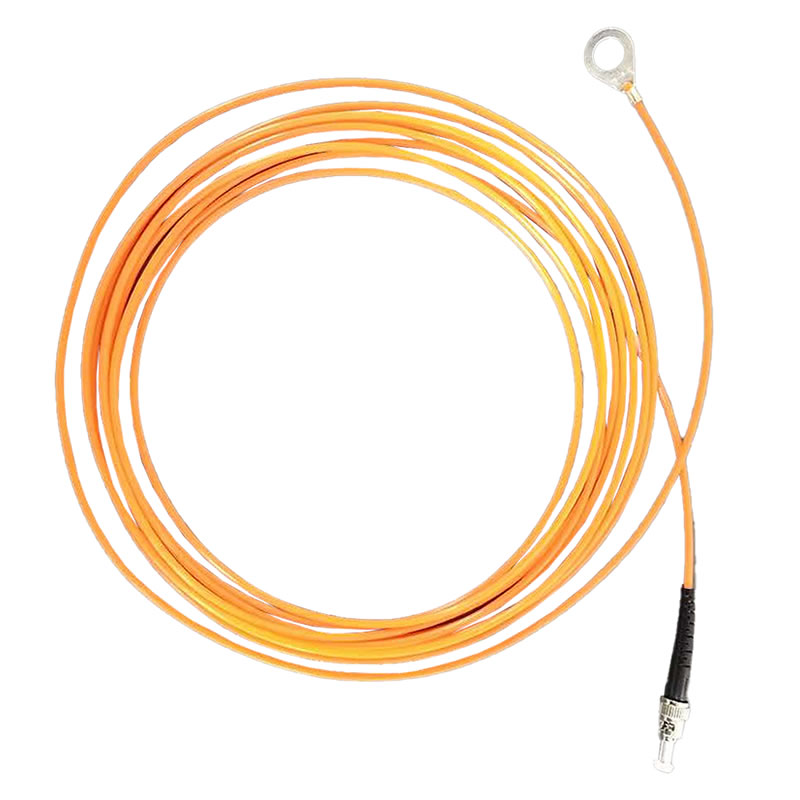
طول كابل الألياف الضوئية
0-80 امتار standard transmission distance between probe and demodulator unit. Multimode fiber supports installations where demodulator located in remote control rooms or separate equipment areas. Custom lengths up to 150 meters available.
Probe Physical Dimensions
2-3قطر مم standard probe size fits within tight clearances on اتصالات بسبار, محطات قواطع الدائرة, and cable lugs. Custom probe geometries available including flat-pad designs for large contact surfaces and needle probes for confined spaces.
العزل الكهربائي
Ceramic or glass-reinforced polymer encapsulation provides complete electrical isolation. Withstand voltage >100كيلو فولت لكل اللجنة الانتخابية المستقلة 60664-1 بروتوكولات الاختبار. Suitable for direct mounting on energized conductors in 500محطات فرعية كيلو فولت.
Operational Lifespan
أعظم من 25 اعوام proven in field deployments since 1990s. Rare-earth phosphors exhibit no degradation under continuous excitation. Fiber optic cable rated for >40-عمر الخدمة سنة.
System Channel Capacity
1-64 القنوات per demodulator unit with modular configuration. Systems scalable from single-panel monitoring to complete substation coverage using distributed demodulator architecture.
واجهة الاتصالات
RS485 مودبوس RTU/TCP standard protocol enables integration with SCADA systems, الشركات المحدودة العامة, ومنصات إدارة المباني. Optional protocols: اللجنة الانتخابية المستقلة 61850, بروفيبوس موانئ دبي, DNP3, OPC تعميم الوصول إلى الخدمات.
خيارات التخصيص
All parameters customizable based on application requirements including extended temperature ranges, specialized probe mounting hardware, حاويات مقاومة للانفجار (اتيكس, IECEx), and custom communication protocols.
7. How Are Temperature Monitoring Points Configured in High Voltage Switchgear?
مفاتيح الجهد العالي (110كيلو فولت-500 كيلو فولت) monitoring strategies prioritize current-carrying contacts and connections where thermal anomalies develop:
Circuit Breaker Moving and Fixed Contacts
ثَبَّتَ مجسات درجة حرارة الألياف الضوئية on both stationary and moving contact assemblies. In SF6 puffer-type breakers, probes mount on contact fingers or tulip contacts. Rotating arc contacts require specialized flexible fiber assemblies. Typical installations monitor 2-4 points per pole (6-12 points for three-phase).
Busbar Joints and Connection Bars
Monitor all bolted busbar connections, particularly at expansion joints and phase-to-phase crossovers. Aluminum busbar installations require higher monitoring density due to cold-flow characteristics. مُستَحسَن: one sensor per connection point in critical feeders, one sensor per 3-4 connections in non-critical circuits.
Disconnect Switch Contact Blades
Isolator switches typically feature knife-blade contacts entering jaw-type receivers. Install probes on both blade tip and jaw contact surfaces. Pantograph-type disconnects require monitoring at pivoting joints and sliding contact points.
نهايات الكابلات والبطانات
Monitor cable lug connections to قاطع الدائرة terminals and busbar takeoff points. Outdoor terminations experience greater temperature fluctuation requiring baseline establishment. تقوم تركيبات جلبة الحائط بمراقبة المحطات الداخلية والخارجية.
المكونات الداخلية لمجموعة المفاتيح الكهربائية GIS/SF6
المفاتيح الكهربائية المعزولة بالغاز يقدم تحديات فريدة من نوعها – يجب أن تخترق أجهزة الاستشعار العبوات المغلقة. يتم توجيه المجسات عبر ممرات التغذية الإيبوكسي أو منافذ الفحص المعدلة. مراقبة الاتصالات المتحركة, اتصالات منزلقة, ومفاصل القضبان داخل حجرات الغاز. خليج GIS النموذجي 145 كيلو فولت: 12-16 نقاط مراقبة درجة الحرارة.
اتصالات محول الصك
المحولات الحالية (ط م) ومحولات الجهد (VT) يتم مراقبة الاتصالات الثانوية في تطبيقات القياس والحماية الهامة. تتطلب التوصيلات الأساسية في المحطات الفرعية الخارجية الخاضعة للتعرض البيئي المراقبة.
8. What Are the Critical Monitoring Locations in Medium Voltage Switchgear (10كيلو فولت-35 كيلو فولت)?

مفاتيح الجهد المتوسط تضم أكبر قاعدة مثبتة على مستوى العالم. تتضمن تكوينات المراقبة القياسية:
10كيلو فولت المفاتيح الكهربائية المكسوة بالمعدن
قواطع دوائر ثابتة أو من النوع الدرجي مع قضيب توصيل منفصل, قاطع الدائرة, ومقصورات الكابلات:
- اتصالات بسبار: مفاصل القضبان الرئيسية, اتصالات فرعية لطعنات قاطع الدائرة (2-3 أجهزة الاستشعار لكل خليج)
- محطات قواطع الدائرة: Load-side and line-side terminals, particularly on high-current feeders >400A (2 أجهزة الاستشعار لكل الكسارة)
- إنهاء الكابلات: Cable lug connections to breaker or busbar, heat-shrink termination body surface (1-2 sensors per cable)
الوحدات الرئيسية الدائرية (RMU)
مدمج المفاتيح الكهربائية for distribution networks require strategic monitoring:
- Load Break Switches: Moving and fixed contacts in both ring and transformer feeder positions
- Busbar Tees: Three-way busbar junctions where ring conductors connect
- Cable Boxes: Separable connector interfaces and cable terminations
Typical 12kV RMU installation: 8-12 temperature points for comprehensive coverage.
C-GIS (Compact Gas-Insulated Switchgear)
SF6-insulated compact switchgear combines advantages of air-insulated and GIS technologies:
- Internal Contacts: Fiber probes route through sealed feedthroughs to monitor circuit breaker and switch contacts
- اتصالات بسبار: Bolted joints within gas compartments
- External Terminations: Cable box connections and transformer links
Vacuum Circuit Breaker Monitoring
قواطع فراغ exhibit unique thermal characteristics. شاشة:
- Vacuum bottle external terminals (contact temperature inference)
- Operating mechanism connections and linkages
- Shunt trip and closing coil connections
35kV Switchgear Configurations
Higher current ratings and larger conductor sizes create different thermal profiles:
- Busbar Chambers: Segregated busbar compartments with higher density connections
- Breaker Mechanisms: Spring-charged or motor-operated mechanisms with higher contact forces
- Outdoor Terminations: Weather-exposed connections requiring environmental compensation
Solid-Insulated Switchgear
Epoxy-resin insulated switchgear eliminates SF6 but creates monitoring challenges:
- Embedded sensors during manufacturing (limited retrofit capability)
- Surface-mounted probes on accessible terminals and connections
- نقاط انتقال الكابل من العزل الصلب إلى العزل الهوائي
9. Why Do Rectifier Cabinets Require Specialized Temperature Monitoring?
خزائن المعدل تظهر إجهادًا حراريًا أعلى من معدات توزيع التيار المتردد التقليدية بسبب التيارات التوافقية, إجهاد الجهد الناقل DC, وخسائر أجهزة أشباه الموصلات:
وحدات جسر المعدل
تولد مجموعات جسر الثايرستور أو الصمام الثنائي حرارة كبيرة. شاشة:
- كل درجة حرارة تقاطع جهاز أشباه الموصلات (تحقيقات اقتران الحرارية)
- تشير درجات حرارة قاعدة المبدد الحراري إلى أداء نظام التبريد
- وصلات بسبار لإدخال التيار المتردد ومخرج التيار المستمر
مقومات عالية الطاقة (>500كيلوواط) تتطلب عادة 8-12 نقاط درجة الحرارة لكل مجموعة الجسر.
اتصالات محول المعدل
تعمل التيارات التوافقية على زيادة لف المحولات ودرجات الحرارة الطرفية:
- المحطات الأولية: عروات اتصال الإدخال تعاني من التسخين التوافقي
- المحطات الثانوية: تيار أعلى يحمل وصلات إخراج التيار المستمر
- اضغط على جهات الاتصال المتغيرة: إذا كان المحول يتضمن تغيير الصنبور عند التحميل
DC Busbar Joints
Direct current creates different contact phenomena than AC:
- Electromigration at connection interfaces increases resistance over time
- Polarity-dependent oxidation patterns
- Higher continuous current density than AC-rated equipment
توصية: Monitor every bolted DC bus connection in systems >100A continuous current.
Filter Capacitor Terminals
Harmonic filtering capacitors carry significant ripple current:
- Terminal connection points susceptible to loosening from vibration
- Internal capacitor temperature inference from terminal measurements
- Early detection of capacitor degradation through temperature trending
Cooling System Integration
Rectifier cabinet monitoring systems should integrate with forced-air or liquid cooling control:
- Fan speed modulation based on component temperatures
- Cooling system failure detection through abnormal temperature rise rates
- تحسين الطاقة عن طريق تقليل التبريد غير الضروري
مراقبة التيار التوافقي
أبعد من درجة الحرارة, تستفيد منشآت المعدل من:
- تحليل التوافقيات الحالية باستخدام مجسات ملف Rogowski
- العلاقة بين المحتوى التوافقي والملامح الحرارية
- التنبؤ بالشيخوخة الحرارية للمحولات والموصلات
10. What Additional Parameters Should Be Monitored Beyond Temperature?
شامل مراقبة حالة المفاتيح الكهربائية يدمج تقنيات الاستشعار المتعددة المحسنة لمعلمات محددة:
التفريغ الجزئي (بي دي) رصد
طرق الكشف:
- أجهزة الاستشعار بالموجات فوق الصوتية: كشف الانبعاثات الصوتية من تفريغ الاكليل, تتبع السطح, والفراغات الداخلية. نطاق التردد 20-100 كيلو هرتز. قم بالتثبيت على الألواح الخارجية أو مباشرة على البطانات/العوازل.
- تردد عالي جدًا (التردد فوق العالي) أجهزة الاستشعار: الانبعاثات الكهرومغناطيسية في نطاق 300 ميجا هرتز - 3 جيجا هرتز. تمييز الضوضاء متفوقة في تركيبات نظم المعلومات الجغرافية. يتطلب وضع هوائي داخلي.
- الجهد الأرضي العابر (تي في): كشف غير تطفلي عبر أداة التوصيل السعوية على أسطح العلبة. تقنية الفحص الفعالة لتحديد مصادر PD.
قيمة التطبيق: تكتشف مراقبة PD تدهور العزل 6-18 أشهر قبل حدوث عطل حراري أو كهربائي. حاسمة بالنسبة للمفاتيح الكهربائية القديمة (>20 years service) and equipment with known insulation weaknesses.
SF6 Gas Density and Purity Monitoring
Intelligent Density Sensors: Replace mechanical density switches with electronic transmitters providing:
- Continuous density measurement (مقابل. discrete alarm points)
- Temperature-compensated readings
- Leak rate calculation through trend analysis
- Remote communication (4-20ملي أمبير, مودبوس) to SCADA
Gas Purity Analysis: Decomposition product monitoring (SOF2, SO2F2, SO2, H2S) indicates arcing activity and insulation breakdown. Gas chromatography sensors detect contamination at ppm levels.
مراقبة الرطوبة
Capacitive Humidity Sensors: Monitor relative humidity in air-insulated compartments. Excessive moisture (>60% ر) accelerates corrosion and reduces surface flashover voltage.
Dewpoint Sensors: Critical for GIS/C-GIS installations – dewpoint monitoring ensures gas moisture content remains below -20°C to prevent insulator contamination.
تحميل المراقبة الحالية
Rogowski Coil Sensors: خفيف الوزن, flexible current sensors providing:
- Non-contact installation (clamp around busbar/cable)
- Wide dynamic range (1A to 10,000A+)
- Harmonic current measurement capability
- No saturation issues like iron-core CTs
Hall Effect Sensors: Direct-reading DC and AC current measurement for rectifier cabinet التطبيقات.
Correlation with Temperature: Current data contextualizes temperature readings – expected load-related temperature rise versus abnormal heating at same current level indicates developing fault.
Circuit Breaker Mechanical Condition Monitoring
Travel Time Measurement: Opening and closing operation duration indicates mechanism degradation, قضايا التشحيم, or contact wear.
Contact Travel Sensors: Linear position transducers measure contact stroke and velocity profile – early detection of mechanical binding or spring degradation.
تحليل الاهتزازات: Accelerometers on breaker mechanism detect abnormal vibration patterns indicating loose components or misalignment.
تحليل التوقيع الحالي للملف: Monitoring of trip/close coil current waveforms reveals mechanical resistance changes and interlock problems.
11. How Is Multi-Parameter Condition Monitoring System Architecture Designed?
Sensor Layer Architecture
Deploy distributed sensors optimized for each parameter:
- مجسات الألياف الضوئية الفلورسنت for temperature (this document’s focus)
- Ultrasonic/UHF sensors for partial discharge
- Intelligent electronic sensors for SF6, رطوبة, حاضِر
- Mechanical position/vibration transducers
Edge Data Acquisition
Panel-Level Data Concentrators: Industrial edge computing gateways installed per switchgear lineup collect:
- Fiber optic demodulator outputs (temperature channels)
- PD sensor analog/digital signals
- Environmental sensor data
- Breaker mechanism status inputs
Local Processing: Edge devices perform preliminary analysis:
- Threshold alarm generation
- Data compression and buffering
- Protocol conversion for diverse sensors
- Time synchronization across all channels
البنية التحتية للاتصالات
Fieldbus Integration:
- RS485 مودبوس RTU: Standard for industrial reliability, يدعم ما يصل إلى 32 devices per segment, 1200m maximum distance
- اللجنة الانتخابية المستقلة 61850: Substation automation standard enabling peer-to-peer communication and standardized data models
- بروفيبوس موانئ دبي: Common in European industrial installations
- Ethernet/IP or Modbus TCP: Modern installations with Ethernet infrastructure
تكامل SCADA: Condition monitoring systems interface with existing supervisory control platforms via:
- DNP3 protocol for utility applications
- OPC UA for vendor-neutral industrial integration
- Proprietary SCADA drivers for legacy systems
Centralized Monitoring Platform
On-Premise Software: Dedicated condition monitoring applications providing:
- Real-time parameter visualization and trending
- Multi-parameter correlation analysis
- Automated alarm management and escalation
- Historical data archiving and reporting
- Predictive analytics and maintenance scheduling
الاتصال السحابي (خياري): Secure data transmission to cloud platforms for:
- Multi-site fleet monitoring
- Advanced analytics and machine learning
- Mobile access and remote expert consultation
12. What Installation Methods Apply to Live Switchgear Equipment?
Live Working Procedures for Fiber Optic Probe Installation
التخطيط قبل التثبيت:
- Arc flash hazard assessment and PPE determination
- Verification of probe compatibility with equipment voltage class
- Preparation of installation-specific work procedures
- Coordination with system operators for load transfer if required
Probe Attachment Methods:
- Adhesive Bonding: High-temperature epoxy or thermal-conductive compounds affix probes to flat busbar surfaces. Surface preparation critical – degrease and abrade contact area.
- Compression Mounting: Spring-loaded clips or saddle clamps hold probes against curved conductors. Stainless steel hardware with electrical insulation.
- Embedded Installation: For new equipment or during major maintenance, probes embedded in connection hardware or molded into contacts.
توجيه كابلات الألياف الضوئية:
- الحفاظ على الحد الأدنى من نصف قطر الانحناء (20mm for glass fiber)
- Secure cables away from moving components and sharp edges
- Use cable glands and grommets when penetrating panel walls
- Segregate fiber cables from power wiring in separate raceways
Demodulator Installation Location
المتطلبات البيئية:
- درجة حرارة: 0-50°C ambient (بعض النماذج -20 إلى +60 درجة مئوية)
- رطوبة: <90% RH غير التكثيف
- Vibration isolation from switchgear mechanical operations
- Adequate ventilation for convection cooling
خيارات التركيب:
- DIN rail mounting in control cabinet or relay panel
- Wall-mount enclosure adjacent to switchgear lineup
- 19-inch rack installation in centralized equipment room
System Commissioning and Verification
Sensor Baseline Establishment:
- Record ambient temperature and initial readings for all probes
- Compare readings across similar connection points (phase-to-phase consistency)
- Document equipment loading during baseline measurement
تكوين عتبة التنبيه:
- منصة 1 إنذار مسبق: Temperature 10-15°C above baseline (informational logging)
- منصة 2 تحذير: Temperature 20-30°C above baseline (operator notification)
- منصة 3 إنذار: Temperature 40-50°C above baseline or absolute 80°C (maintenance action required)
- منصة 4 شديد الأهمية: درجة حرارة >90-105درجة مئوية (immediate load transfer or shutdown)
اختبار الاتصالات:
- Verify data polling from SCADA or monitoring software
- Test alarm transmission and acknowledgment procedures
- Confirm time synchronization across distributed sensors
13. Global Customer Application Case Studies
دراسة الحالة 1: 500kV GIS Substation – Utility Power Transmission
نطاق المشروع: National grid utility retrofitted مراقبة درجة حرارة الألياف الضوئية to existing 500kV gas-insulated substation experiencing historical busbar connection failures.
تكوين النظام:
- 96 fluorescent fiber optic temperature sensors across 6 GIS bays
- نقاط المراقبة: اتصالات قاطع الدائرة, مفاصل بسبار, افصل واجهات التبديل
- 3 وحدات المستخلص (32 قنوات لكل منهما) مع اللجنة الانتخابية المستقلة 61850 اندماج
Installation Methodology: Sensors installed during routine maintenance outages using epoxy feedthroughs through SF6 compartment walls. Zero modifications to primary equipment.
النتائج التشغيلية:
- Detected developing fault in busbar bolted joint 8 قبل أشهر من الفشل المتوقع
- Temperature trending revealed gradual 15°C rise over 6-month period
- Scheduled maintenance during planned outage prevented unplanned 500kV line trip
- Estimated avoided cost: $2.5M (استبدال المعدات + emergency mobilization + lost transmission revenue)
دراسة الحالة 2: Data Center 10kV Medium Voltage Distribution
Customer Requirements: Hyperscale data center operator required continuous monitoring of redundant 10kV المفاتيح الكهربائية feeding UPS systems and generator transfer switches.
تصميم النظام:
- 48 temperature monitoring points across main-tie-main switchgear configuration
- المراقبة المشتركة: درجة حرارة الألياف البصرية + Rogowski coil current sensors
- Integration with building management system via Modbus TCP
Key Monitoring Locations:
- Utility service entrance cable terminations
- Generator breaker and transfer switch contacts
- UPS feeder breaker terminals
- Main busbar tie connections
Documented Benefits:
- Correlation analysis between load current and temperature established predictive thermal models
- Identified cable termination with 12°C temperature differential versus other phases – preventive retorquing avoided potential failure
- تم تحسين توفر النظام من 99.95% ل 99.99% after monitoring implementation
دراسة الحالة 3: Steel Mill Rectifier System – Industrial Application
Application Environment: Electric arc furnace rectifier cabinet supplying 50MW DC power to smelting operations. Harsh environment with high electromagnetic interference, غبار, والاهتزاز.
حل المراقبة:
- 64-channel fiber optic system monitoring thyristor bridge modules, DC busbar connections, ومحطات المحولات
- Immunity to 50kA fault current EMI critical for sensor reliability
- Combined temperature and harmonic current monitoring
Operational Experience:
- تم اكتشاف عطل في مروحة التبريد من خلال نمط ارتفاع غير طبيعي في درجة حرارة المبدد الحراري
- تم تحديد وصلة مثبتة بحافلة DC فضفاضة تعمل على تطوير نقطة اتصال تبلغ 35 درجة مئوية عند 80% حمولة
- تم منع الانقطاع القسري الذي قد يكلف 150.000 دولارًا في الساعة من الإنتاج المفقود
- تم تحسين جدولة الصيانة بناءً على الحالة الحرارية الفعلية مقابل الفواصل الزمنية المستندة إلى الوقت
دراسة الحالة 4: محطات طاقة الرياح البحرية 35 كيلو فولت، نهايات الكابلات تحت سطح البحر
التحديات الفريدة: منصات توربينات الرياح البحرية ذات الوصول المحدود وبيئة بحرية قاسية. تخضع نهايات الكابلات للتدوير الحراري والتعرض للرطوبة.
مراقبة التنفيذ:
- 32 أجهزة استشعار الألياف الضوئية تراقب نهايات واجهة الكابلات/المفاتيح الكهربائية تحت سطح البحر
- الاتصال عبر الأقمار الصناعية لبيانات المراقبة إلى مركز التحكم البري
- تغليف المسبار بمادة الإيبوكسي البحرية لمقاومة التآكل
القيمة المسلمة:
- Remote condition assessment eliminates costly and weather-dependent offshore crew visits
- Early detection of cable termination degradation enables maintenance during planned weather windows
- 25-year sensor lifespan aligns with expected platform service life
دراسة الحالة 5: Semiconductor Fab 480V/13.8kV Distribution
أهمية التطبيق: Semiconductor manufacturing requires absolute power reliability – single voltage sag can scrap entire production lot ($500K-2M loss).
مراقبة شاملة:
- Temperature monitoring on all 480V main distribution busbar and 13.8kV utility service switchgear
- Integration with facility power quality monitoring system
- Automated alarm escalation procedures
تأثير الأعمال:
- Zero unplanned power outages since monitoring implementation (36-month track record)
- Proactive component replacement based on thermal trending
- Insurance premium reduction achieved through demonstrated reliability improvement
الأسئلة المتداولة (الأسئلة المتداولة)
الأسئلة المتداولة 1: ما هي تكلفة الاستثمار الأولية لنظام مراقبة درجة حرارة الألياف الضوئية الفلورية? كيف يمكنني الحصول بسرعة على الاقتباس?
الاستثمار الأولي ل نظام مراقبة درجة حرارة الألياف الضوئية يختلف بناء على عدة عوامل:
مقياس النظام: يحدد عدد نقاط المراقبة متطلبات سعة مزيل التشكيل. نموذجي 10 كيلو فولت مفاتيح الجهد المتوسط مراقبة التثبيت 8-16 اتصالات حرجة (محطات قواطع الدائرة, مفاصل بسبار, إنهاء الكابلات) يتطلب وحدة مزيل تشكيل ذات 16 قناة.
هيكل التكلفة:
- وحدة المستخلص: $3,000-$8,000 اعتمادا على عدد القنوات (1-64 القنوات) وخيارات الاتصال
- مجسات الألياف الضوئية الفلورية: $150-$300 لكل جهاز استشعار بما في ذلك كابل الألياف
- ملحقات التثبيت: تركيب الأجهزة, صناديق الوصلات, إدارة الكابلات – تقريبًا 15-20% من تكلفة المعدات
- الهندسة والتكليف: تصميم النظام, الإشراف على التثبيت, اختبار – يختلف حسب تعقيد المشروع
استثمارات المشروع النموذجية:
- تركيب صغير (8-مراقبة النقطة, تشكيلة المفاتيح الكهربائية واحدة): $5,000-$8,000 دولار أمريكي
- تركيب متوسط (32-مراقبة النقطة, لوحات متعددة): $12,000-$20,000 دولار أمريكي
- محطة فرعية كبيرة (100+ نقاط, مزيلات تشكيل متعددة): $40,000-$80,000 دولار أمريكي
الحصول على عرض أسعار مخصص: اتصل بفريق هندسة التطبيقات لدينا من خلال www.fjinno.net مع المعلومات التالية لتوليد الاقتباس السريع:
- Switchgear type and voltage class (10كيلو فولت, 35كيلو فولت, 110كيلو فولت, الخ.)
- Number of panels or bays requiring monitoring
- Preferred monitoring points (اتصالات قاطع الدائرة, اتصالات بسبار, إنهاء الكابلات)
- Existing SCADA/communication infrastructure
- Project timeline and any specific technical requirements
We provide detailed quotations within 24-48 hours including equipment specifications, installation recommendations, and lifecycle cost analysis demonstrating total ownership value.
الأسئلة المتداولة 2: Our switchgear is aging equipment. Can we retrofit a condition monitoring system? How much downtime is required?
أجهزة استشعار الألياف الضوئية الفلورسنت are ideal for retrofitting legacy switchgear installations – this represents 60-70% of our project portfolio.
التوافق التحديثي:
- Minimal Physical Modifications: Compact 2-3mm diameter probes fit within existing clearances. No structural alterations to primary equipment required.
- Non-Invasive Installation: Sensors attach to busbar surfaces, العروات الكابل, and breaker terminals using adhesive bonding or mechanical clips. Zero drilling or welding on energized components.
- Adaptable to Any Vintage: Successfully deployed on switchgear manufactured from 1960s to present. Compatible with air-insulated, SF6, and vacuum technologies.
Downtime Requirements:
Typical Installation Duration per Switchgear Panel:
- Pre-outage preparation (توجيه الألياف, demodulator mounting): Performed energized – zero downtime
- De-energization for probe installation: 2-4 hours depending on number of monitoring points
- System testing and re-energization: 30-60 دقائق
Total Outage Window: 3-5 hours per switchgear bay – typically accommodated during routine maintenance schedules or off-peak periods.
Live-Working Options: For critical infrastructure where outages are prohibitively expensive, our certified technicians can install sensors on energized equipment using hot-stick methods and appropriate PPE. This approach eliminates downtime but requires specialized procedures and safety protocols.
التنفيذ المرحلي: Large installations can be commissioned in stages – monitoring most critical feeders first, then expanding to complete coverage over multiple maintenance windows. System remains operational during phased deployment.
Aging Equipment Benefits: Retrofit monitoring is particularly valuable for aged switchgear (>20 years service) where failure probability increases exponentially. Temperature monitoring extends equipment service life 5-10 years through condition-based maintenance versus premature replacement.
الأسئلة المتداولة 3: Will the monitoring system integrate with our existing automation infrastructure? ما هي بروتوكولات الاتصال المدعومة?
ملكنا fiber optic temperature monitoring demodulators support comprehensive protocol libraries ensuring compatibility with virtually all SCADA, DCS, PLC, وأنظمة إدارة المباني:
Standard Communication Interfaces:
RS485 مودبوس RTU: التكوين الافتراضي – البروتوكول الصناعي الأكثر انتشارًا. يدعم طوبولوجيا متعددة الإفلات (يصل إلى 32 devices per segment), 1200-الحد الأقصى لمسافة الكابل متر, والتحقق من الأخطاء بشكل قوي. مثالية للمنشآت الصغيرة والاتصال المباشر بـ PLC.
البروتوكولات القائمة على إيثرنت:
- مودبوس تكب / إب: متغير إيثرنت من Modbus يتيح التكامل مع البنية التحتية الحديثة للشبكة المحولة
- اللجنة الانتخابية المستقلة 61850: المعيار الدولي لأتمتة المحطات الفرعية – يوفر نماذج بيانات موحدة, التواصل بين نظير إلى نظير, والتقارير المستندة إلى الأحداث. مطلوب لتطبيقات شبكة المرافق في العديد من الولايات القضائية.
- OPC تعميم الوصول إلى الخدمات (العمارة الموحدة): معيار اتصالات صناعي محايد للبائع يدعم التبادل الآمن للبيانات ونماذج المعلومات المعقدة
البروتوكولات الاختيارية/المخصصة:
- DNP3: شائع في تطبيقات المرافق في أمريكا الشمالية – يدعم البيانات المختومة بالوقت والإبلاغ عن الأحداث
- بروفيبوس موانئ دبي: السائدة في الأتمتة الصناعية الأوروبية
- باك نت: Building automation protocol for commercial facility integration
- إم كيو تي تي: Lightweight messaging protocol for IoT and cloud connectivity
Integration Methodology:
- System Survey: Our engineers assess your existing automation architecture (SCADA vendor, PLC types, طوبولوجيا الشبكة)
- Protocol Selection: Recommend optimal communication method based on bandwidth requirements, network security policies, and real-time performance needs
- Data Mapping: Configure monitoring system data points to align with your naming conventions and SCADA database structure
- الاختبار والتحقق من الصحة: Comprehensive integration testing including alarm transmission, data accuracy verification, and failover scenarios
Typical Integration Timeline: 1-3 days for standard protocols (مودبوس, اللجنة الانتخابية المستقلة 61850). Custom protocols may require 1-2 weeks for development and testing.
Remote Access Capability: Systems can be configured for secure remote monitoring via VPN, cellular gateways, or cloud platforms – enabling multi-site fleet monitoring and remote expert diagnostics.
الأسئلة المتداولة 4: What technical support and warranty coverage do you provide if sensors or equipment fail?
كقائد fiber optic temperature monitoring system manufacturer, we provide comprehensive support throughout equipment lifecycle:
Warranty Coverage:
Standard Warranty: 3 years comprehensive coverage on all system components including:
- Fiber optic demodulator units (إلكترونيات, إمدادات الطاقة, وحدات الاتصالات)
- Fluorescent fiber optic temperature probes and fiber optic cables
- Mounting hardware and accessories
Extended Warranty Options: 5-year and 10-year extended coverage available – particularly valuable for remote installations where equipment access is difficult.
Coverage Terms:
- Zero-cost replacement of defective components
- Expedited shipping for critical installations (next-day air freight available)
- On-site technical support for warranty repairs if required
Technical Support Services:
24/7 التشخيص عن بعد:
- دعم عبر الهاتف والبريد الإلكتروني مع متوسط وقت استجابة يبلغ ساعتين
- الوصول إلى النظام عن بعد (مع إذن العميل) لاستكشاف الأخطاء وإصلاحها
- التوجيه في الوقت الحقيقي للمشغلين أثناء ظروف الخطأ
الخدمة في الموقع:
- إيفاد مهندسي الخدمة الميدانية داخل 48 ساعات للمنشآت الحرجة
- زيارات الصيانة الوقائية (يوصى به سنويًا أو نصف سنوي)
- تقييمات صحة النظام وتحسينه
إجراء استبدال المستشعر:
في حالة نادرة لفشل مسبار الألياف الضوئية:
- يؤكد التشخيص عن بعد على المستشعر مقابل المستشعر. قضية المزيل
- يتم شحن المسبار البديل داخل 24 الساعات
- اكتمل التثبيت خلال فترة الصيانة التالية المتاحة (عادة 2-4 انقطاع ساعة)
- تعمل إعادة معايرة النظام واختباره على التحقق من صحة الوظيفة
إحصائيات الموثوقية: معدل الفشل الميداني <0.5% سنويا لتحقيقات الألياف الضوئية و <1% للإلكترونيات المستخلص على أساس 15+ سنوات البيانات الأساسية المثبتة. معظم “الفشل” traced to installation errors or external damage rather than component defects.
Training and Documentation:
- Comprehensive operation and maintenance manuals
- On-site or web-based training for maintenance personnel
- Video troubleshooting guides and knowledge base
Spare Parts Stocking: For large installations or critical infrastructure, we recommend maintaining spare sensor inventory and can provide consignment stock programs.
الأسئلة المتداولة 5: We’re uncertain which parameters require monitoring for our specific switchgear. How can we obtain professional engineering guidance?
أفضل مراقبة حالة المفاتيح الكهربائية system design requires application-specific engineering analysis. We provide complimentary consultation services:
Free Application Assessment Services:
Remote Consultation (No Site Visit Required):
- Provide switchgear specifications (الشركه المصنعه, نموذج, فئة الجهد, التقييمات الحالية)
- Review existing maintenance records and failure history
- تحديد مستوى الأهمية ومخاطر الانقطاع المقبولة
- تلقي توصيات نقطة المراقبة الأولية داخل 2-3 أيام العمل
المسح في الموقع (للمنشآت المعقدة أو الكبيرة):
- تقييم خط الأساس للتصوير الحراري باستخدام كاميرات الأشعة تحت الحمراء المعايرة
- الفحص البصري لحالة المفاتيح الكهربائية وإمكانية الوصول إليها
- تقييم الأجهزة الحالية والبنية التحتية للاتصالات
- تصميم نظام مراقبة تفصيلي مع رسومات موقع أجهزة الاستشعار
التسليمات الهندسية:
- استراتيجية مراقبة مخصصة: المعلمات الموصى بها (درجة حرارة, التفريغ الجزئي, كثافة SF6, الخ.) على أساس نوع المعدات, عمر, والملف التشغيلي
- كمية الاستشعار والتنسيب: تحسين اختيار نقاط المراقبة لتحقيق التوازن بين شمولية التغطية وقيود الميزانية
- اقتراح بنية النظام: تكوين المستخلص, طوبولوجيا الاتصالات, نهج التكامل مع أنظمة الأتمتة الحالية
- تحليل التكلفة والعائد: الانخفاض المتوقع في احتمال الفشل, وفورات في تكاليف الصيانة, وتجنب نفقات الانقطاع
- خطة التنفيذ: خيارات النشر المرحلي, متطلبات الانقطاع, الجدول الزمني للتثبيت
توصيات المراقبة النموذجية حسب التطبيق:
محطات المرافق: درجة حرارة + مراقبة التفريغ الجزئي للعزل الشامل وتقييم الحالة الحرارية
المنشآت الصناعية: درجة حرارة + تحميل المراقبة الحالية لتحليل الارتباط والصيانة التنبؤية
المباني التجارية: تركز مراقبة درجة الحرارة على المغذيات المهمة مع تكامل اختياري لجودة الطاقة
مراكز البيانات: مراقبة متعددة المعلمات (درجة حرارة, حاضِر, رطوبة) مع مسارات الاتصالات الزائدة عن الحاجة
عملية المشاركة:
اتصل بفريق هندسة التطبيقات لدينا عبر www.fjinno.net مع معلومات المشروع الأساسية:
- نوع المنشأة وموقعها
- جرد المفاتيح الكهربائية (مستويات الجهد, عدد اللوحات)
- مخاوف محددة أو أوضاع الفشل التاريخي
- الجدول الزمني للمشروع ومعلمات الميزانية
داخل 24 الساعات, ستتلقى جدولة الاستشارة الأولية والتوجيه الأولي. مقترحات التقييم التفصيلية المقدمة في غضون أسبوع واحد.
تقييم عدم الالتزام: خدمات الاستشارات الهندسية تقدم بدون تكلفة للمشاريع المؤهلة. نحن نستثمر في تصميم النظام المناسب لأن أنظمة المراقبة المحددة بشكل صحيح توفر أقصى قيمة ورضا العملاء.
لا تزال لديك أسئلة حول مراقبة حالة المفاتيح الكهربائية?
فريقنا الفني جاهز لمساعدتك في التصميم الأمثل مراقبة درجة حرارة الألياف الضوئية الحل لتطبيقك المحدد. سواء كنت تراقب المفاتيح الكهربائية ذات الجهد العالي, توزيع الجهد المتوسط, خزائن المعدل, أو المعدات الصناعية المتخصصة, نحن نقدم إرشادات الخبراء بدءًا من الاستشارة الأولية وحتى الدعم التشغيلي طويل المدى.
اتصل بنا اليوم من خلال www.fjinno.net ل:
- تقييم مجاني لنظام مراقبة حالة المفاتيح الكهربائية
- توصيات مخصصة لنقطة المراقبة
- المواصفات الفنية التفصيلية وعروض الأسعار
- دعم هندسة التطبيقات وتصميم النظام
لا تنتظر فشل المعدات – تنفيذ مراقبة الحالة الاستباقية اليوم!
تنصل
المعلومات الواردة في هذه المقالة هي للأغراض التعليمية والإعلامية العامة فقط. While we strive to ensure accuracy based on current industry standards and best practices as of January 2026, specific مراقبة حالة المفاتيح الكهربائية requirements vary significantly based on equipment manufacturer, بيئة التشغيل, regulatory jurisdiction, and application criticality.
المواصفات الفنية for fluorescent fiber optic temperature monitoring systems (including measurement ranges, دقة, سعة القناة, وبروتوكولات الاتصال) represent typical performance parameters. Actual specifications should be verified through detailed product datasheets and confirmed during project engineering phase.
إجراءات التثبيت described in this guide are general recommendations. All electrical work on المفاتيح الكهربائية ذات الجهد العالي must be performed by qualified personnel following applicable safety regulations (NFPA 70E, IEEE 1584, local electrical codes), manufacturer instructions, and facility-specific procedures. Arc flash hazard analysis and appropriate personal protective equipment are mandatory for all energized work.
تكامل النظام capabilities depend on compatibility verification with specific SCADA, DCS, or automation platforms. Protocol support should be confirmed during procurement specification.
Economic analyses and failure statistics cited represent industry averages compiled from multiple sources. Actual costs, failure rates, and monitoring system benefits vary based on equipment condition, operating practices, and facility-specific factors.
This article does not constitute professional engineering advice for your specific installation. For safety-critical applications or complex projects, consult with licensed electrical engineers and certified switchgear monitoring specialists.
Product and company names mentioned may be trademarks of their respective owners. لا يوجد أي تأييد أو انتماء ضمني ما لم ينص على ذلك صراحة.
الامتثال التنظيمي وتبقى المسؤولية على عاتق مالك/مشغل المعدات. التحقق من أن أنظمة المراقبة المقترحة تلبي المعايير المعمول بها (اللجنة الانتخابية المستقلة, IEEE, أنسي, القوانين المحلية) لاختصاصك والتطبيق.
للحصول على إرشادات فنية خاصة بالمشروع وتوصيات احترافية مصممة وفقًا لمتطلبات مراقبة حالة المفاتيح الكهربائية لديك, يرجى الاتصال بفريق هندسة التطبيقات لدينا من خلال www.fjinno.net.
آخر تحديث: يناير 19, 2026

مستشعر درجة حرارة الألياف البصرية, نظام مراقبة ذكي, الشركة المصنعة للألياف البصرية الموزعة في الصين
 |
 |
 |