 INNO fibre optic temperature sensors ,temperature monitoring systems.
A winding temperature indicator (WTI) is an indirect “estimation” thermometer based on top-oil temperature and load current, while a fiber optic temperature monitoring system is a “direct measurement” device that reads the true hot-spot temperature inside the winding. The core differences come down to five points:
- Measuring principle: The temperature controller estimates winding temperature from top-oil temperature plus a load-current thermal image; the fiber optic monitoring system measures the real temperature directly at the hot spot.
- Response & accuracy: The WTI thermometer carries thermal-model error and thermal lag; the fiber optic system responds in real time with higher accuracy, reflecting the true instantaneous hot-spot temperature.
- Electrical safety & immunity: The WTI is an electrical temperature monitoring device; fiber optic is purely optical, fully immune to EMI, and introduces no extra electrical fault point into the winding.
- Functional role: The temperature controller combines indication, cooling control and trip protection; the monitoring system focuses on high-accuracy hot-spot monitoring and data-driven condition assessment.
- Applications: The WTI suits standard temperature indication and protection control; the fiber optic monitoring system suits high-value assets, dynamic rating and condition-based maintenance.
Table of Contents
1. What Is a Transformer Winding Temperature Indicator (WTI)?

The Winding Temperature Indicator (WTI) is the most common temperature monitoring device on a power transformer. This thermometer does not contact the winding directly. Instead, it uses a temperature sensor placed in the top oil, combined with a heating element driven by load current, to simulate the temperature rise of the winding above the oil — and thereby “calculate” the winding temperature. A typical electrical thermal-image temperature controller such as the BWR2 Winding Temperature Indicator is a representative product of this principle.
1.1 Basic Structure of the WTI Temperature Controller
A WTI typically consists of an oil-temperature sensing element, a thermal-image heating unit powered by the secondary current of a bushing CT, and a pointer or digital temperature indicator. The temperature rise produced by the heating unit is added to the oil temperature to represent the winding-to-oil hot-spot temperature difference.
1.2 Typical Functions of the Temperature Monitoring Device
A WTI is usually more than an indicator. This temperature controller typically integrates several adjustable setpoint contacts used to stage cooling fans and oil pumps, raise over-temperature alarms, and trigger trip protection when a dangerous temperature is reached. This makes it a functional link in the transformer’s protection and control loop rather than a pure measuring thermometer.
2. What Is a Fiber Optic Temperature Monitoring System?
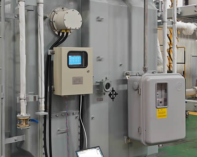
A fiber optic temperature monitoring system uses sensors embedded inside the winding to measure the true hot-spot temperature directly. It is a purely optical measurement: the probe carries no voltage and is unaffected by electromagnetic fields, so this monitoring device can be safely located in the high-potential winding region. For oil-filled equipment, the oil-immersed transformer fiber optic temperature system is a typical application.
2.1 Core Components of the Hot-Spot Monitoring System
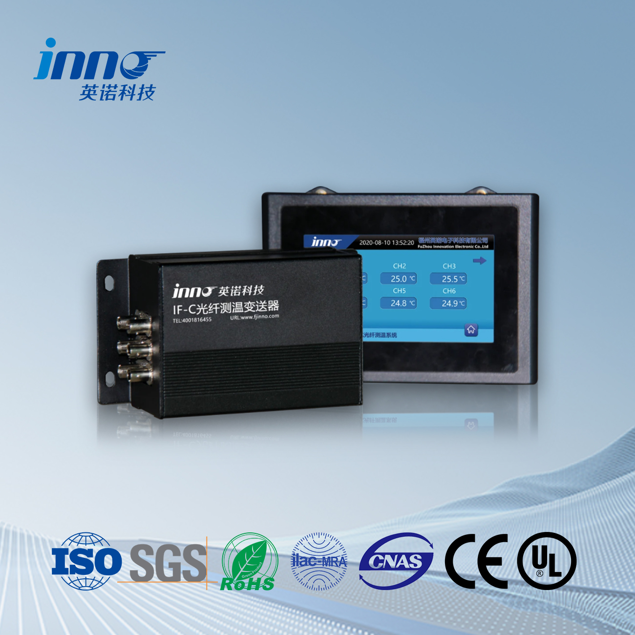
A complete fiber optic temperature monitoring system generally includes three parts: fiber optic temperature sensors embedded in the winding hot-spot region, a signal-conditioning instrument that demodulates the optical signal, and a real-time data acquisition and alarm module. The temperature outputs can be integrated into SCADA / DCS platforms.
2.2 Measurement Characteristics of the Fiber Optic Temperature Device
Because measurement takes place directly at the hot spot, the fiber optic monitoring system reflects the real, present winding temperature rather than an estimate. It offers fast response, high accuracy, and complete immunity to EMI, and requires virtually no recalibration over its service life.
3. Working Principle of the Temperature Controller vs Monitoring Device
The most fundamental difference is this: one temperature is “calculated,” the other is “measured.”
3.1 The WTI Thermal-Image Temperature Principle
The core of a WTI temperature controller is thermal imaging: it assumes the winding hot-spot temperature rise above top oil is proportional to the square of the load current, and uses a calibrated heating element to reproduce that rise. The result depends on the model assumptions and setpoint calibration, making this thermometer inherently an indirect estimate.
3.2 The Fiber Optic Direct Hot-Spot Measurement Principle
Fiber optic temperature sensors are pre-installed at the hot-spot location between the conductor and the insulation, directly sensing the actual temperature at that point and converting it into a reading via optical demodulation. This monitoring system relies on no oil temperature, current, or thermal model, eliminating the source of model error.
4. Hot-Spot Temperature Accuracy and Response Comparison

Accuracy and response speed are where the two temperature systems differ most clearly.
4.1 Error Sources and Thermal Lag of the Temperature Controller
A WTI temperature reading is influenced by oil-temperature measurement, thermal-image calibration, and the rate of load change. During rapid load swings, the time constant of the thermal image introduces significant thermal lag, so the indicated temperature trails the actual hot spot and may deviate by several degrees Celsius.
4.2 Real-Time Response and Accuracy of the Monitoring System
A fiber optic temperature sensor sits directly at the hot spot, so temperature changes are captured almost instantly, with no lag from a thermal model. Combined with high-resolution demodulation, the monitoring system’s accuracy generally surpasses the thermal-image thermometer, making it better suited to applications that need a precise grasp of hot-spot temperature dynamics.
5. Function and Application Comparison of the Two Temperature Systems
Beyond principle and accuracy, the two temperature monitoring methods also differ in their functional focus and best-fit scenarios.
5.1 Functional Focus of Controller vs Monitoring System
The WTI temperature controller emphasizes “control and protection”: integrated indication, staged cooling control, alarms and trip make it part of the protection loop. The fiber optic monitoring system emphasizes “measurement and monitoring”: high-accuracy hot-spot temperature data supports condition assessment, trend analysis and life management, leaning toward data-level health monitoring.
5.2 Asset and Scenario Fit for Each Temperature Device
For standard distribution and small-to-medium power transformers, the indication and protection functions of a WTI temperature controller are usually sufficient. For high-value assets such as large main transformers, converter transformers and generator step-up transformers — or where dynamic rating and condition-based maintenance are required — the true hot-spot temperature data from a fiber optic monitoring system delivers higher value.
6. Side-by-Side Temperature Monitoring Comparison Table
| Criterion | Winding Temperature Indicator (WTI) | Fiber Optic Temperature Monitoring System |
|---|---|---|
| Measuring method | Indirect (thermal-image estimate) | Direct (optical, inside the winding) |
| Temperature type | Equivalent winding temp. from oil + current | True winding hot-spot temperature |
| Accuracy | Calibration-dependent, can deviate several °C | High, typically ±1 °C class |
| Response speed | Thermal lag, trails actual change | Near real-time, no model lag |
| EMI immunity | Electrical, affected by EMI | Purely optical, fully immune |
| Electrical safety | Live measuring circuit | Non-conductive probe, safe at high potential |
| Control / protection | Yes: cooling control, alarm, trip | Monitoring-focused, can drive alarms |
| Remote communication | Available on some models | Native, easy SCADA / DCS integration |
| Measuring points | Typically single equivalent point | Multi-point (multiple phases / locations) |
| Maintenance / calibration | Periodic verification needed | Essentially calibration-free, long-term stable |
| Installation stage | Can be retrofitted in service | Best embedded during manufacturing |
| Typical application | Standard indication & protection control | High-value assets, dynamic rating, CBM |
7. How to Choose Between a WTI Thermometer and a Fiber Optic System
As a guide, the choice between the two temperature systems follows from your actual requirements.
7.1 When to Choose a WTI Temperature Controller
When the main need is standard temperature indication, staged cooling control and over-temperature trip protection, and the asset value and accuracy requirements are at a general level, a WTI temperature controller is usually sufficient. It is a mature, field-retrofittable temperature monitoring device and the standard choice for distribution and small-to-medium transformers.
7.2 When to Choose a Fiber Optic Monitoring System
When you need the true, real-time winding hot-spot temperature — for example to enable dynamic rating, implement condition-based maintenance, or protect critical assets such as large main transformers, converter transformers and generator step-up units — direct fiber optic temperature measurement provides data a WTI thermometer cannot replace.
7.3 Using Both Temperature Systems Together
On many high-value transformers the two are not mutually exclusive: the WTI temperature controller continues to handle cooling control and trip protection, while the fiber optic monitoring system performs high-accuracy direct hot-spot temperature measurement and condition-data acquisition. Together they form a more complete temperature monitoring strategy.
8. Customer Cases
The following anonymized cases summarize how utilities and industrial operators have deployed these temperature monitoring solutions and the results they achieved.
| Industry / Region | Asset | Solution Deployed | Outcome |
|---|---|---|---|
| Grid utility, Northern Europe | 220 kV main transformer fleet | Fiber optic hot-spot system + retained WTI | Enabled dynamic rating; ~8% additional usable capacity confirmed without exceeding insulation limits. |
| Renewable energy, Western US | Wind-farm step-up transformers | Fiber optic multi-point monitoring | Detected early hot-spot drift on two units; avoided an unplanned outage during peak generation season. |
| Heavy industry, Central Europe | Arc-furnace supply transformers | WTI for trip/cooling + fiber optic for monitoring | EMI-immune readings under harsh duty; cooling staged more accurately, reducing fan run-time. |
| Distribution operator, Southern Europe | MV distribution transformers | WTI retrofit program | Standardized over-temperature protection across the fleet at low cost; simplified maintenance. |
| HVDC converter station, Asia-Pacific | Converter transformers | Embedded fiber optic system | Validated thermal design with direct hot-spot data; supported condition-based maintenance scheduling. |
Cases are presented anonymously to protect customer confidentiality. Results vary by load profile, transformer design and operating conditions.
9. Customer Reviews
| Rating | Reviewer | Review |
|---|---|---|
| ⭐⭐⭐⭐⭐ | Asset Manager, Transmission Utility | “Adding fiber optic hot-spot monitoring alongside our existing WTIs gave us the confidence to dynamically rate several key transformers. The direct temperature readings finally told us what the windings were actually doing.” |
| ⭐⭐⭐⭐⭐ | Maintenance Engineer, Renewable Power | “Installation during manufacturing was straightforward and the sensors have been completely stable. No recalibration, no EMI issues — exactly what we needed at a remote step-up substation.” |
| ⭐⭐⭐⭐ | Reliability Lead, Heavy Industry | “Under arc-furnace duty the electrical readings used to wander. The optical temperature measurement is rock-solid. We kept the WTI for tripping, which was the right call for our protection scheme.” |
| ⭐⭐⭐⭐⭐ | Substation Supervisor, Distribution Operator | “For our distribution fleet the WTI retrofit was the practical choice — affordable, easy to install in service, and it standardized our over-temperature protection across hundreds of units.” |
| ⭐⭐⭐⭐⭐ | Project Engineer, HVDC Station | “Embedding the fiber optic sensors during the build let us verify the thermal design with real hot-spot temperature data. The condition-based maintenance value alone justified the investment.” |
10. Frequently Asked Questions
Can a WTI and a fiber optic temperature monitoring system be used together?
Yes. In many high-value transformers the WTI temperature controller handles cooling control and trip protection, while the fiber optic monitoring system provides direct, real-time hot-spot temperature measurement and condition data. The two are complementary, not mutually exclusive.
Can a fiber optic system replace the trip protection function of a WTI?
A fiber optic monitoring system is built around high-accuracy temperature measurement and monitoring. Its outputs can drive alarms and integrate with protection logic, but the dedicated indication, cooling-control and trip relays traditionally provided by a WTI temperature controller are usually retained.
Which option is more suitable for an existing in-service transformer?
A WTI thermometer can be retrofitted relatively easily because it relies on top-oil temperature and load current. Fiber optic temperature sensors are best embedded during manufacturing, so retrofitting them into in-service windings is difficult and existing units often keep the WTI.
How large is the accuracy gap between the two temperature methods?
A WTI is a thermal-model estimate and can lag during fast load changes, deviating by several degrees Celsius. A fiber optic temperature sensor measures the hot spot directly and typically achieves higher accuracy with near-instant response.
Which method has lower maintenance cost?
Fiber optic temperature sensors are passive and immune to EMI, requiring little or no recalibration over their service life. A WTI temperature controller uses electrical components and periodic verification, so over the long term fiber optic monitoring can require less maintenance effort.

Fiber optic temperature sensor, Intelligent monitoring system, Distributed fiber optic manufacturer in China
 |
 |
 |