 INNO fibre optic temperature sensors ,temperature monitoring systems.
Transformer insulation aging is the gradual chemical, thermal, and mechanical deterioration of solid and liquid dielectric materials inside a transformer over its operating life. Because dielectric breakdown in service is frequently preceded by long-term thermal stress, winding temperature and localized winding hot-spot temperature are primary indicators of how rapidly insulation capability is being consumed. High operating temperatures accelerate polymer chain scission in cellulose paper and thermal embrittlement in cast-resin or synthetic insulation systems.
Temperature, however, does not act in isolation. Moisture, oxygen, contamination, electrical stress, mechanical vibration, and repeated load cycling combine with heat to reduce dielectric and mechanical strength before a fault occurs. Continuous temperature monitoring—paired with proper thermal-limit interpretation—helps engineers detect abnormal heating early and slow premature insulation degradation.
1. What Is Transformer Insulation Aging?

Transformer insulation aging describes the irreversible loss of mechanical tensile strength and dielectric integrity in winding insulation systems over time. In oil-immersed transformers, cellulose paper and pressboard undergo depolymerization and release aging byproducts into the oil; in dry-type transformers, solid resin, varnish, and high-temperature fibers gradually harden, shrink, or develop micro-cracks under sustained thermal and electrical stress.
Once insulation materials lose mechanical elasticity, the winding becomes vulnerable to conductor movement during through-fault currents, load switching, or mechanical vibration. What often appears as a sudden electrical short circuit is commonly the final stage of cumulative transformer thermal aging that weakened turn-to-turn or phase-to-ground barriers over years of operation.
Engineering takeaway: Insulation rarely fails solely from chronological age; effective service life depends on cumulative thermal, environmental, and electrical stress experienced by the winding.
2. How Winding Temperature Drives Thermal Aging
Winding temperature governs the rate of chemical reactions inside solid insulation materials. When a transformer operates within its design thermal envelope, aging progresses slowly and predictably; when winding temperature rises above normal baselines during sustained overloads or cooling impairments, chemical degradation accelerates nonlinearly.
Evaluating thermal stress requires separating material capability from live operating readings. Reviewing transformer insulation class and temperature rise clarifies how thermal class ratings (such as Class A, B, F, or H) define maximum system capability rather than a consequence-free daily operating temperature. Operating continuously near the upper boundary of an insulation class leaves less thermal margin for ambient spikes or harmonic heating and speeds up long-term material wear.
| Thermal Quantity | Relationship to Insulation Aging | Operational Interpretation |
|---|---|---|
| Ambient Temperature | Sets the external cooling baseline and alters available thermal margin | High ambient air or room temperature increases absolute winding temperature at the same electrical load |
| Top-Oil Temperature | Indicates bulk heat transfer from core and coils into the cooling medium | Reflects overall thermal loading in liquid-filled units but lags behind rapid conductor heating |
| Average Winding Temperature | Represents overall conductor thermal state across the coil | Useful for design verification, though it can mask concentrated local overheating |
| Winding Hot-Spot Temperature | Tracks the highest localized temperature in the winding structure | Determines the fastest local rate of transformer insulation aging and thermal risk |
3. Why Local Winding Hot Spots Accelerate Insulation Breakdown
Overall transformer reliability is limited by the weakest, most thermally stressed region of the winding rather than the cool regions of the coil. Dedicated winding hot-spot temperature monitoring is essential because localized conductor segments can operate significantly hotter than average winding or bulk oil readings indicate.
Hot spots typically form near upper winding sections where cooling oil or air is already heated, inside restricted cooling ducts, around high-current tap or terminal leads, or in regions exposed to concentrated stray eddy-current and harmonic losses. Because local insulation at the hot spot experiences the highest absolute temperature, paper embrittlement or resin micro-cracking progresses fastest at that specific point even while average transformer temperatures appear normal.
Engineering takeaway: Average winding temperature and top-oil readings can look acceptable while a localized winding hot spot quietly consumes insulation life.
4. Non-Thermal Factors That Combine With Heat to Age Insulation
While temperature is the primary catalyst for transformer thermal aging, several environmental and operational factors interact with heat to accelerate dielectric deterioration:
- Moisture ingress: Water in oil-paper systems hydrolyzes cellulose chains much faster at elevated temperatures, while humidity in dry-type units reduces surface insulation resistance.
- Oxygen and oil oxidation: Dissolved oxygen reacts with heated insulating oil to form organic acids and sludge that attack cellulose fibers and clog cooling passages.
- Blocked cooling paths: Dust buildup on dry-type coils or sludge deposition in oil ducts restricts heat dissipation and raises local winding gradients.
- Harmonic currents: Nonlinear loads increase eddy-current and stray losses in winding conductors, generating extra localized heat not reflected by fundamental load current alone.
- Repeated thermal cycling: Frequent load swings cause differential expansion and contraction between copper or aluminum conductors and adjacent insulation, loosening clamping pressure or delaminating solid resin.
- Mechanical and electrodynamic forces: Short-circuit currents and core vibration stress brittle insulation, turning thermal micro-cracks into dielectric faults.
- Surface contamination and partial discharge: Conductive dust, salt fog, or chemical vapors promote surface tracking and localized partial discharge that erode solid barriers.
5. Oil-Immersed vs Dry-Type Transformer Insulation Aging
Oil-immersed and dry-type transformers use different dielectric systems and therefore exhibit different aging mechanisms and monitoring priorities. In liquid-filled units, routine transformer oil temperature measurement works alongside winding indicators and oil quality diagnostics, whereas dry-type units rely directly on winding and air-duct temperature sensing.
| Comparison Aspect | Oil-Immersed Transformer Insulation | Dry-Type Transformer Insulation |
|---|---|---|
| Primary Insulation Materials | Cellulose kraft or thermally upgraded paper, pressboard, and mineral oil or ester fluid | Epoxy cast resin, aramid paper, glass-fiber composites, mica, and VPI varnishes |
| Dominant Thermal Aging Mechanism | Cellulose depolymerization, loss of tensile strength, gas evolution, and oil oxidation | Resin thermal embrittlement, micro-cracking, delamination, and loss of dielectric strength |
| Key Accelerating Co-Factors | Moisture in paper, dissolved oxygen, acid formation, and radiator or pump cooling faults | Enclosure ventilation blockage, dust accumulation, moisture condensation, and thermal cycling |
| Primary Thermal Quantities Monitored | Ambient temperature, top-oil temperature, winding temperature, and local hot-spot temperature | Ambient room temperature, phase winding temperatures, core temperature, and local hot spots |
6. How Temperature Monitoring Helps Slow Insulation Aging
Online temperature monitoring cannot reverse past chemical degradation, but it directly controls future aging rate by preventing avoidable thermal excursions. Accurate transformer winding temperature measurement gives operators real-time visibility into how loading, ambient conditions, and cooling performance affect the winding.
Integrating temperature sensors into a dry-type transformer monitoring system or substation transformer monitoring platform supports four practical life-extension actions: automating cooling fans or pumps before heat accumulates, balancing or shifting load during peak ambient periods, identifying blocked air ducts or fouled radiators through historical trend comparison, and triggering early alarms before winding hot spots exceed design limits.
7. Comparing Temperature Monitoring Methods for Insulation Protection
Selecting an appropriate monitoring method requires understanding whether a device provides an indirect thermal estimate, a standard accessible point reading, or a direct internal hot-spot measurement.
| Monitoring Method | What It Measures | Main Strength for Insulation Protection | Main Limitation |
|---|---|---|---|
| WTI / Thermal Model | Indirectly simulated or calculated winding temperature using oil temperature and load current | Provides continuous estimated thermal tracking and standard cooling/alarm control without internal coil probes | Relies on model assumptions and external inputs; cannot directly detect an unexpected local winding defect |
| PT100 / RTD Sensor | Direct temperature at accessible low-voltage slots, air ducts, or thermometer pockets | Stable, cost-effective electrical measurement well suited for standard dry-type winding ducts and oil pockets | Metallic sensor and leads lack high-voltage isolation for direct placement on bare high-voltage conductors |
| Fluorescent Fiber Optic Sensor | Direct point temperature at the installed optical probe tip | Complete electrical isolation and EMI immunity allow direct contact measurement at high-voltage winding hot spots | Internal winding embedding is best planned during new transformer manufacture or major coil rebuilds |
When direct measurement inside high-voltage coils is required, a fluorescent fiber optic temperature sensor provides passive optical sensing without conductive wires. Point-type fluorescent sensors measure discrete critical locations where probes are installed, which differs from distributed temperature sensing (DTS) systems designed for long linear cable routes.
Engineering takeaway: Indirect indicators and RTDs cover general thermal protection, while point-type fluorescent fiber optic sensors provide direct local temperature verification inside high-voltage electromagnetic fields.
8. FJINNO Fiber Optic Temperature Monitoring Options
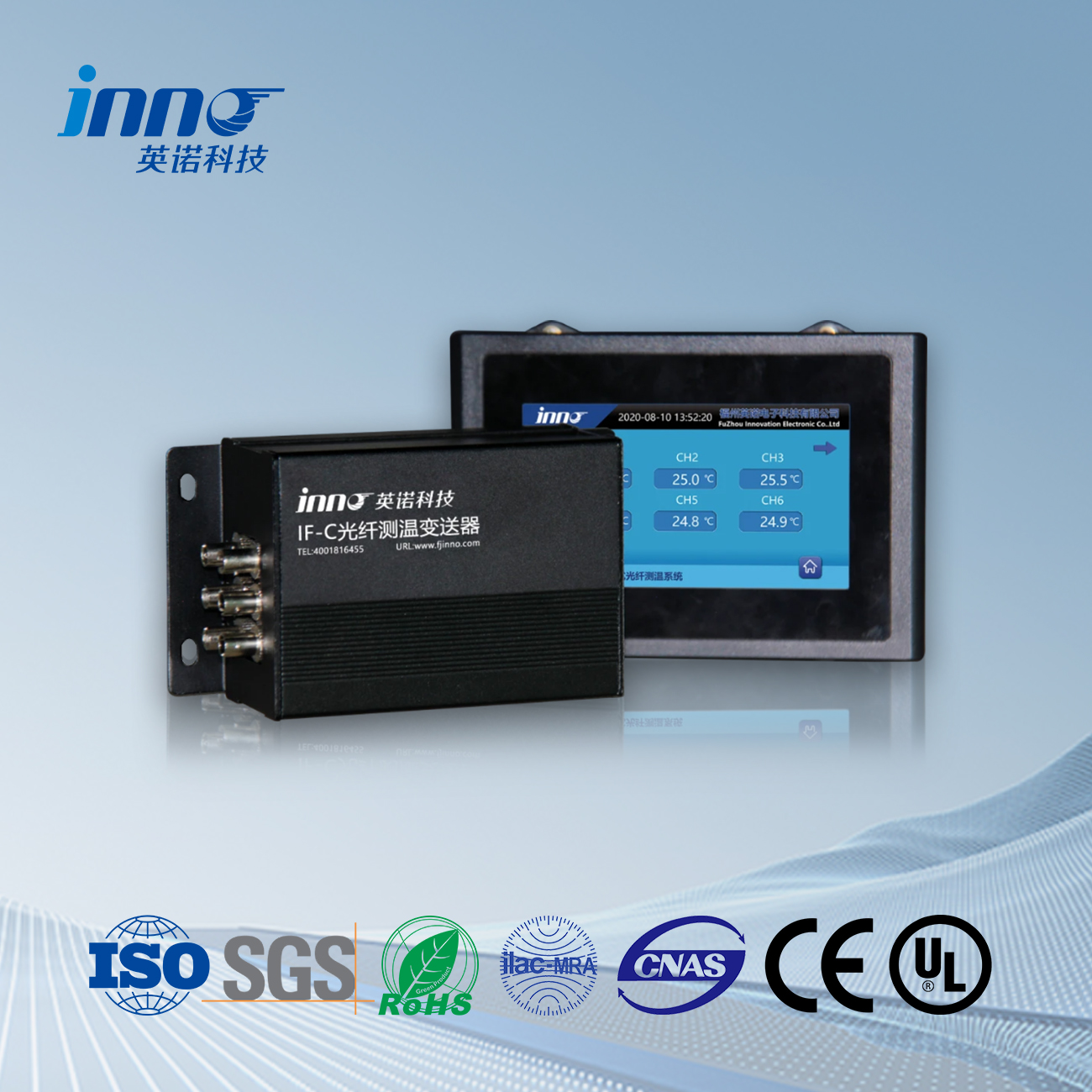
Matching monitoring hardware to a transformer project involves confirming channel count, temperature range, accuracy, communication protocol, and probe installation method. FJINNO supplies point-type fluorescent fiber optic probes and multi-channel monitoring transmitters for both dry-type and oil-immersed transformer applications, including a dedicated dry-type transformer winding fiber optic temperature measurement system and scalable multi-channel hosts.
| Product | Channels | Temperature Range | Accuracy | Resolution | Response Time | Communication | Power Supply | Typical Use |
|---|---|---|---|---|---|---|---|---|
| Dry-Type Transformer Winding Fiber Optic Temperature Measurement System | 1–18 customizable | -40°C to +260°C (customizable) | ±1°C (customizable) | 0.1°C | <1 s measurement cycle | RS485 / Modbus; 4–20 mA output | AC/DC 220V | Dry-type transformer winding hot-spot monitoring, automatic cooling fan control, and alarm/trip protection |
| Fluorescent Fiber Optic Temperature Sensor | — | — | — | — | — | — | — | All-dielectric point temperature probe with 100 kV high-voltage isolation and EMI immunity for transformer windings |
| 6-Channel Fiber Optic Temperature Monitoring Device | 6 optical sensors (1–64 customizable) | -40°C to +240°C (customizable) | ±1.0°C (±0.5°C available) | 0.1°C | ≤5 s | RS485 Modbus-RTU; 4–20 mA output | AC/DC 220V | Three-phase transformer winding hot-spot tracking, core monitoring, and switchgear thermal protection |
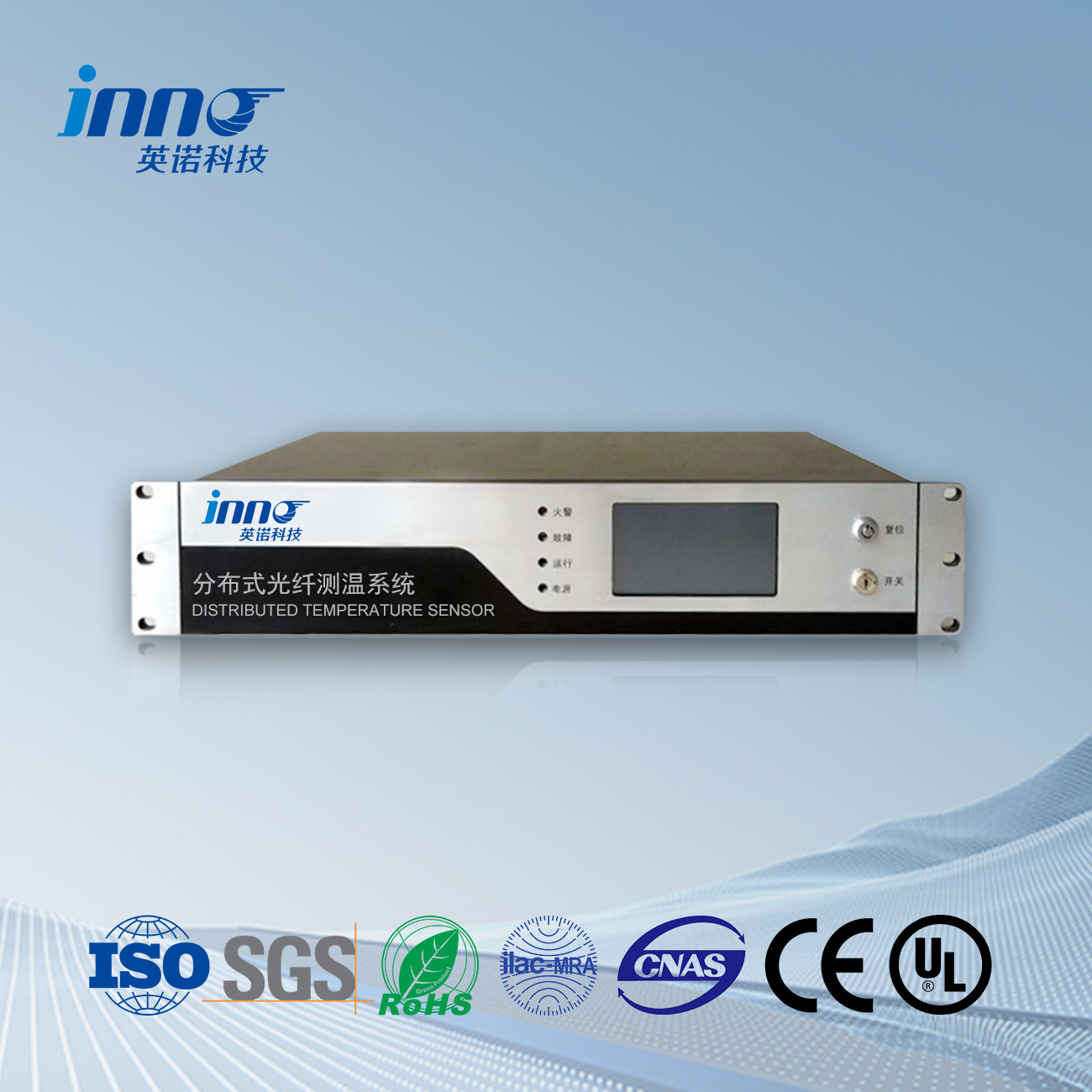
| 64-Channel Fluorescent Fiber Optic Temperature Measurement System | 1–64 customizable | -40°C to +240°C (customizable) | ±1°C (customizable) | 0.1°C | — | RS485 / Modbus; 4–20 mA output | AC/DC 220V | Multi-point power transformer winding monitoring and centralized substation temperature acquisition |
9. Using Temperature Trends and Alarms to Prevent Premature Aging
Waiting for a single high-temperature trip event is an ineffective way to manage insulation life. Properly configured transformer over-temperature alarm stages should work alongside historical trend analysis so operators can intervene when abnormal thermal patterns first appear.
Alarm and cooling control setpoints should always follow transformer manufacturer limits, insulation thermal class, sensor position, and project protection rules rather than generic temperature tables. In day-to-day operation, engineers should watch for early warning signs of increasing thermal stress: a rising winding-to-ambient temperature differential under comparable load, persistent phase-to-phase temperature imbalance, slower cooling recovery after peak load, or a steady upward drift in a local hot-spot channel over consecutive seasons.
10. Practical Transformer Insulation Life Protection Checklist
- □ Confirm transformer type (oil-immersed or dry-type) and winding insulation construction
- □ Verify insulation thermal class and manufacturer temperature-rise and hot-spot limits
- □ Establish baseline winding, oil, and ambient temperature profiles under normal loading
- □ Identify critical winding hot-spot locations during new design or major refurbishment
- □ Select RTD/PT100, WTI, or point-type fluorescent fiber optic sensors based on voltage clearance
- □ Confirm required monitoring channel count across phases, windings, core, and ambient
- □ Configure cooling fan or pump automation and multi-stage over-temperature alarms
- □ Integrate RS485 Modbus or 4–20 mA temperature data into SCADA for long-term trend logging
- □ Inspect ventilation paths, air ducts, radiators, and cooling fans on a regular maintenance schedule
- □ Review phase-to-phase temperature comparisons and seasonal trends under comparable load
11. Example: Detecting Abnormal Thermal Stress Before Insulation Failure
Consider a hypothetical example involving an industrial transformer supplying a facility with variable production loads. Over several months, online monitoring records show that while load current and ambient temperature remain consistent with previous operating cycles, one winding temperature channel gradually develops a higher temperature rise than the other two phases.
Although the absolute reading has not yet crossed the emergency trip threshold, maintenance engineers flag the diverging trend during a routine review. Comparing the elevated channel against phase current balance, ambient records, and cooling fan operation confirms that electrical loading is symmetrical. A scheduled offline inspection reveals partial cooling-path restriction and dust buildup around the hotter winding section; cleaning the cooling channels and verifying terminal connections restores normal operating temperature and halts accelerated local insulation aging.
Final Thoughts
Transformer insulation aging is a cumulative process driven primarily by local winding temperature, hot-spot severity, and operating environment. While thermal class ratings define the design capability of solid or liquid-paper insulation systems, actual insulation longevity depends on keeping day-to-day winding temperatures and transient hot spots within safe engineering margins.
Combining proper cooling maintenance with reliable temperature monitoring gives operators actionable visibility into winding thermal stress. Whether an application calls for conventional indicators, PT100 sensors in accessible ducts, or point-type fluorescent fiber optic probes embedded at high-voltage hot spots, tracking real thermal trends helps prevent premature insulation breakdown and unplanned outages.
Frequently Asked Questions
What is the main cause of transformer insulation aging?
Sustained high temperature is the primary driver of transformer insulation aging because heat accelerates chemical degradation in both cellulose paper and solid resin systems. In field operation, thermal stress is often compounded by moisture, oxygen, cooling blockage, harmonic heating, and repeated load cycling that weaken dielectric and mechanical strength together.
Why does winding hot-spot temperature matter more than average temperature for aging?
Insulation breakdown typically initiates at the single most degraded location rather than uniformly across the entire winding. Because chemical aging speeds up nonlinearly as temperature rises, the localized conductor region experiencing the highest hot-spot temperature loses mechanical and dielectric strength much faster than the average winding temperature suggests.
Can temperature monitoring extend transformer insulation life?
Temperature monitoring does not reverse existing chemical wear, but it helps preserve remaining insulation life by enabling early intervention. Real-time winding and hot-spot data allow automated cooling control, timely load adjustments, and early detection of ventilation or cooling-duct problems before prolonged overheating permanently damages the insulation.
When should fluorescent fiber optic sensors be used to monitor insulation thermal stress?
Point-type fluorescent fiber optic temperature sensors are best used when engineers need direct temperature measurement at high-voltage winding hot spots where metallic PT100 sensors cannot safely be placed. Because optical probes are electrically isolated and immune to electromagnetic interference, they are commonly integrated during new transformer manufacture or major coil rebuilds.
Need Help Monitoring Transformer Winding Temperature to Protect Insulation Life?
Designing a reliable temperature monitoring setup starts with your transformer construction and thermal protection requirements. Share your transformer type, insulation class, winding arrangement, number of measurement points, new-build or retrofit status, communication protocol, and alarm requirements so FJINNO engineers can recommend a suitable monitoring solution. Discuss Your Project

Fiber optic temperature sensor, Intelligent monitoring system, Distributed fiber optic manufacturer in China
 |
 |
 |