 INNO fibre optic temperature sensors ,temperature monitoring systems.
- Isolated phase bus (IPB) duct temperature monitoring is the continuous measurement of temperature at critical joints and connection points of the high-current bus that links generators, generator step-up (GSU) transformers and other major electrical equipment.
- Bolted joints, flexible connections, conductor interfaces and terminations can develop abnormal heating from increased contact resistance, looseness, oxidation, installation issues or long-term operating stress.
- Continuous monitoring lets operators identify a developing hot spot before excessive heat affects conductors, insulation, connectors or surrounding equipment.
- Point fiber optic temperature sensors contain no conductive electrical sensing element at the measurement point and are not affected by the strong electromagnetic fields around high-current bus conductors.
- Multi-channel temperature demodulators transmit real-time values, alarms and trends to plant PLC, DCS or SCADA systems, and the monitoring layout can be configured to each IPB design.
Fiber Optic Temperature Monitoring System for Isolated Phase Bus
E-mail: web@fjinno.net
WhatsApp: +8613599070393
- Why Monitor Temperature in Isolated Phase Bus Ducts?
- What is an Isolated Phase Bus?
- What Causes Abnormal Heating in an IPB?
- Critical Temperature Monitoring Points
- Why Fiber Optic Temperature Sensors for IPB Monitoring?
- How Point Fluorescent Fiber Optic Temperature Sensing Works
- Fiber Optic Temperature Monitoring System for Isolated Phase Bus
- Typical IPB Temperature Monitoring Layout
- Choosing the Number of Monitoring Channels
- Alarm Thresholds and Trend Analysis
- Communication and Plant System Integration
- Applications
- Monitoring Configuration Based on Your IPB Design
- Retrofit of Existing Isolated Phase Bus Systems
- Predictive Maintenance Based on Temperature Data
Why Monitor Temperature in Isolated Phase Bus Ducts?

Isolated phase bus ducts carry high current between generators, generator step-up transformers and other major electrical equipment. Bolted joints, flexible connections, conductor interfaces and termination points can develop abnormal heating due to increased contact resistance, installation issues, mechanical looseness, oxidation or long-term operating stress.
Continuous temperature monitoring helps operators identify developing hot spots before excessive heating affects conductors, insulation, connectors or surrounding equipment.
- Early Hot Spot Detection:
A rising contact resistance at a joint shows up as a temperature trend long before a failure. Online measurement of electrical joint temperature turns a hidden defect into a visible warning. - Generator Availability:
The generator bus duct is a single path for the full unit output. A fault in the generator transformer connection can take the whole unit out of service, so early detection protects generation availability. - Protection of Nearby Equipment:
Overheated conductor joints can damage adjacent insulation, seals and connected equipment. Monitoring limits the spread of thermal damage. - Maintenance Planning:
Temperature history at each monitored point helps operators decide when to inspect, re-torque or repair a joint, rather than relying only on scheduled outages. - Load Management:
Real-time conductor hot spot monitoring gives operators confidence about loading conditions under high-demand periods.
What is an Isolated Phase Bus?
- Definition:
An isolated phase bus is a high-current bus system in which each phase conductor is enclosed in its own separate metallic enclosure. It is widely used between a generator and its step-up transformer, and to feed auxiliary transformers. - Typical Connections:
Generator terminals, transformer terminals, bolted conductor joints, flexible connections and branch connections to auxiliary equipment. - Operating Conditions:
Very high load current, strong magnetic fields around the conductors, and an enclosed structure that limits access to internal parts. - Monitoring Challenge:
Because the conductors are enclosed and electrically demanding, monitoring at the joints requires sensors that are compatible with high-current, high-field environments.
What Causes Abnormal Heating in an IPB?
- Increased Contact Resistance:
Poor surface contact at bolted joints raises resistance, and heat generated is proportional to the resistance times the current squared. - Mechanical Looseness:
Vibration, thermal cycling and insufficient bolt torque can loosen connections over time. - Oxidation and Surface Degradation:
Contact surfaces can oxidize or degrade, increasing joint resistance. - Installation Issues:
Incorrect assembly, misalignment or contamination during installation or maintenance can leave a joint that heats abnormally. - Long-Term Operating Stress:
Repeated load cycles and thermal expansion stress flexible connections and other joints throughout the life of the plant.
Critical Temperature Monitoring Points
- Bolted Conductor Joints:
Monitor temperature rise caused by increasing contact resistance. - Flexible Connections:
Detect abnormal heating at flexible links exposed to electrical and mechanical stress. - Generator Terminals:
Monitor critical connection points close to the generator output. - Transformer Connections:
Track temperature conditions where the IPB connects to the generator step-up transformer. - Bus Conductor Connections:
Measure hot spots at high-current conductor interfaces and transition points. - Branch and Equipment Connections:
Monitor auxiliary transformer, excitation transformer or other connected equipment where applicable, depending on the project’s IPB structure.
Why Fiber Optic Temperature Sensors for IPB Monitoring?
- Electrical Insulation:
Fiber optic probes contain no conductive electrical sensing elements at the measurement point. - Immunity to Electromagnetic Interference:
Temperature measurements are not affected by the strong electromagnetic fields around high-current bus conductors. - Direct Hot Spot Measurement:
Sensors can be positioned close to selected joints or conductor hot spots according to the installation design. - Multi-Point Monitoring:
Multiple critical locations can be connected to a multi-channel temperature monitoring unit. - Remote System Integration:
Temperature data can be transmitted to plant monitoring, PLC, DCS or SCADA systems through supported communication interfaces.
How Point Fluorescent Fiber Optic Temperature Sensing Works
- Fluorescent Tip:
The end of the optical fiber carries a rare earth fluorescent material that responds only to temperature. - Excitation Light:
A light pulse from the demodulator travels through the fiber and excites the fluorescent material. - Decay Time Measurement:
After excitation, the fluorescence afterglow decays exponentially. The decay time constant is a single-valued function of temperature, so measuring it gives the temperature at the probe tip. - Independent of Light Intensity:
The result depends on the decay time constant and not on light source intensity, transmission loss or coupling changes. - Point Sensing:
Each probe measures the temperature at one defined location. This is different from distributed sensing, which measures along the length of a fiber. Point sensing is well suited to IPB joints, where the hot spot positions are known from the design.
Fiber Optic Temperature Monitoring System for Isolated Phase Bus
System flow:
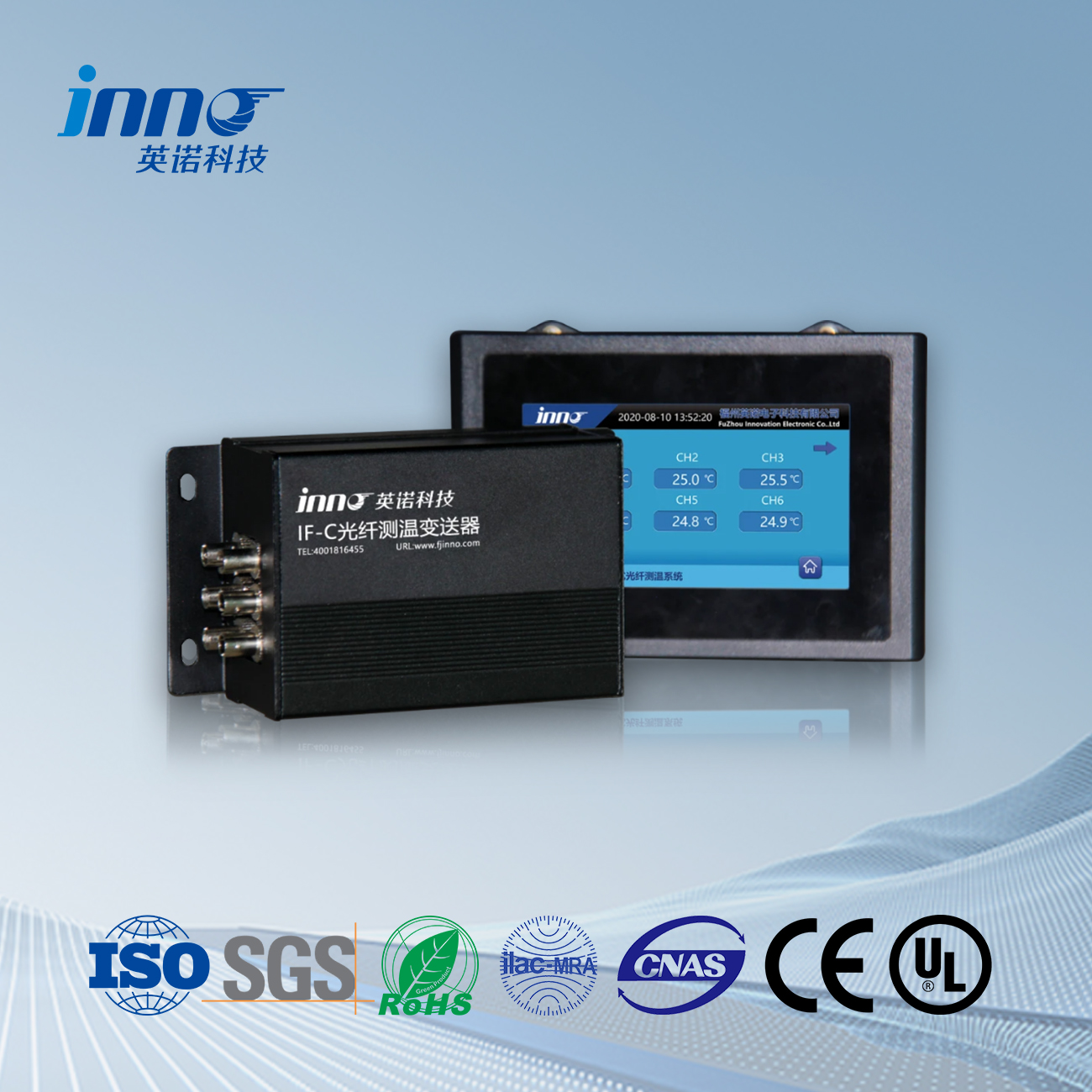
Fiber Optic Temperature Sensor → Fiber Extension Cable → Temperature Transmitter / Demodulator → PLC / DCS / SCADA
The monitoring system uses point fiber optic temperature sensors installed at selected critical positions inside or around the isolated phase bus assembly. Sensor signals are transmitted through optical fiber to a multi-channel temperature demodulator located in a suitable control or monitoring area.
The system can provide real-time temperature values, alarm thresholds, historical temperature trends and communication with the plant monitoring platform, depending on project requirements.
- Fiber Optic Temperature Sensor:
The sensing element at the measurement point. FJINNO offers a range of fluorescent fiber optic temperature sensors, including a fiber optic temperature sensor for busbar and bolt connections and fluorescent probes for other mounting requirements. - Fiber Extension Cable:
Carries the optical signal from the probe to the demodulator. An extension cable for fluorescent fiber optic temperature sensors allows the demodulator to be placed away from the bus, in a suitable control or monitoring area. - Temperature Transmitter / Demodulator:
Converts the optical signal into temperature values, applies alarm thresholds and provides communication outputs. Multi-channel models are available, including three-channel, four-channel, six-channel and nine-channel units. - Local Display (Optional):
A fiber optic temperature measurement LCD display instrument can provide local reading where required. - Plant Monitoring Platform:
PLC, DCS or SCADA systems receive the data for display, historical trending and alarm management.
Typical IPB Temperature Monitoring Layout
A typical generator isolated phase bus monitoring project may install temperature sensors at:
- Generator-side phase A/B/C connections
- Main conductor joints
- Flexible connector positions
- Generator step-up transformer-side phase A/B/C connections
- Branch connections where required
The final number of monitoring channels depends on the IPB structure, number of joints, equipment configuration and customer monitoring requirements.
| Monitoring Location | Example Sensor Arrangement | Purpose |
|---|---|---|
| Generator-side terminals | One or more probes per phase (A / B / C) | Monitor critical connections close to the generator output |
| Main conductor joints | Probes at selected bolted joints on each phase | Detect contact resistance increase |
| Flexible connectors | Probes at flexible link positions on each phase | Detect heating from electrical and mechanical stress |
| GSU transformer-side terminals | One or more probes per phase (A / B / C) | Track temperature where the IPB connects to the GSU transformer |
| Branch connections | Probes as required by the project | Monitor auxiliary or excitation transformer connections where applicable |
The table is an example only. Actual sensor positions are determined according to the IPB drawings and the customer’s monitoring strategy.
Choosing the Number of Monitoring Channels
- Three-Phase Symmetry:
Because an IPB has three separate phases, monitoring points are commonly planned in multiples of three, so that phases A, B and C can be compared at equivalent locations. - Count the Critical Points:
Add up the terminals, bolted joints, flexible connections and branch connections that the customer wants monitored on each phase. - Allow Spare Capacity:
A few spare channels help with future expansion or with adding points after commissioning. - Combine Multiple Units:
Several multi-channel demodulators can be combined for larger projects. For reference, FJINNO’s fiber optic temperature measurement system for generator sets supports up to 64 customizable channels. - No Fixed Quantity:
There is no universal number of points for an IPB. The correct quantity depends on the project.
Alarm Thresholds and Trend Analysis
- Configurable Alarms:
Alarm settings can be configured for each channel according to the project requirements and the limits given by the IPB manufacturer. - Phase Comparison:
Comparing temperatures across phases A, B and C at equivalent positions helps identify a joint that is heating differently from the others. - Trend Against Load:
A joint whose temperature rises faster than load current suggests increasing contact resistance and should be investigated. - Historical Records:
Stored temperature trends support outage planning, root cause analysis and documentation.
Communication and Plant System Integration
- Digital Communication:
FJINNO fiber optic temperature monitoring units provide interfaces such as RS485 with Modbus for integration with PLC, DCS, SCADA or other plant monitoring systems, depending on the selected configuration. - Analog Output:
For systems that need it, 4–20 mA analog current output is available on selected configurations. - Remote Monitoring:
Because the sensing path is optical, the demodulator can be installed in a control or monitoring area away from the bus, and data reviewed remotely. - Configuration Dependent:
Please confirm the required interface with the manufacturer when placing an inquiry.
Applications
- Generator Isolated Phase Bus:
Temperature monitoring between large generators and step-up transformers. See also our fiber optic temperature measurement system for generator sets. - Generator Step-Up Transformer Connections:
Monitoring conductor and connection hot spots near GSU transformer terminals. For transformer-side monitoring, see our guide to transformer temperature monitoring. - Power Plant Main Bus Systems:
Multi-point temperature monitoring for critical high-current electrical connections in power generation facilities. - Industrial High-Current Bus Systems:
Temperature monitoring for selected bus joints and high-current connection points. For metal-enclosed switchgear, see fiber optic temperature measurement for switchgear.
Monitoring Configuration Based on Your IPB Design
Isolated phase bus systems vary significantly in current rating, conductor structure, joint arrangement, enclosure design and available installation space. FJINNO can configure the monitoring solution according to project drawings and actual monitoring points.
Configuration can include:
- Number of temperature monitoring points
- Sensor probe configuration
- Fiber cable length
- Number of monitoring channels
- Alarm settings
- Communication interface
- PLC, DCS or SCADA integration
- Installation accessories and documentation
Information to prepare for an inquiry:
- IPB drawings or a sketch showing the joints and connection points to be monitored
- Number of phases and required monitoring points per phase
- Distance from the sensor positions to the planned demodulator location
- Required alarm logic and communication interface (RS485, Modbus, 4–20 mA, etc.)
- Whether the project is a new installation or a retrofit
Retrofit of Existing Isolated Phase Bus Systems
- Feasibility Factors:
Retrofit feasibility depends on available installation space, access to the required monitoring positions, insulation requirements and the existing IPB structure. - Outage Planning:
Probe installation at conductor joints normally needs the bus to be de-energized and made accessible during a planned outage. - Review Before Selection:
Project drawings or site information should be reviewed before selecting the installation method. - Compact Probes:
Fiber optic probes are small, which helps in locations with limited space.
Predictive Maintenance Based on Temperature Data
- Baseline Building:
Record normal temperatures at each monitored point under different loads to create a reference for each joint. - Deviation Detection:
A point that deviates from its baseline or from the other phases at the same load indicates a developing problem. - Targeted Inspection:
Maintenance teams can focus on the joints that show abnormal trends during the next outage. - Documented History:
Historical data supports condition assessment and long-term asset management of the generator connection.
Relevant Standards and Quality References
Bus temperature limits, test methods and acceptance criteria for isolated phase bus are defined by the IPB manufacturer and the applicable standards. Always follow the current edition of the standard specified for your project.
IEEE C37.23: Standard for Metal-Enclosed Bus
A widely referenced standard for metal-enclosed bus, including isolated phase bus. It covers ratings, temperature considerations and tests. Consult the current edition for project-specific limits.
IEC 61000-4 and GB/T 17626: Electromagnetic Compatibility Testing and Measurement Techniques
Define immunity test methods for electronic equipment. FJINNO’s generator set fiber optic temperature system references these standards for electromagnetic compatibility testing.
ISO 9001:2015: Quality Management Systems
International quality management certification applicable to the manufacture of the monitoring equipment.
Frequently Asked Questions: Isolated Phase Bus Temperature Monitoring
Where should temperature sensors be installed on an isolated phase bus?
Sensors are typically installed at critical joints, flexible connections, conductor interfaces, generator terminals, transformer connections and other locations where abnormal contact resistance may cause local heating. The actual positions should be determined according to the IPB structure and project drawings.
How many temperature monitoring points are required for an IPB system?
There is no fixed number. The required quantity depends on the number of phases, joints, flexible connections, terminal points and the customer’s monitoring strategy.
Can fiber optic sensors operate near high-current bus conductors?
Fiber optic temperature sensing is suitable for electrically demanding environments because the sensing principle is immune to electromagnetic interference and the sensing path can provide electrical isolation.
Can the temperature data be connected to a plant SCADA or DCS system?
Yes. The temperature monitoring unit can provide communication interfaces such as RS485 for integration with PLC, DCS, SCADA or other plant monitoring systems, depending on the selected configuration.
Can existing isolated phase bus systems be retrofitted with temperature monitoring?
Retrofit feasibility depends on available installation space, access to the required monitoring positions, insulation requirements and the existing IPB structure. Project drawings or site information should be reviewed before selecting the installation method.
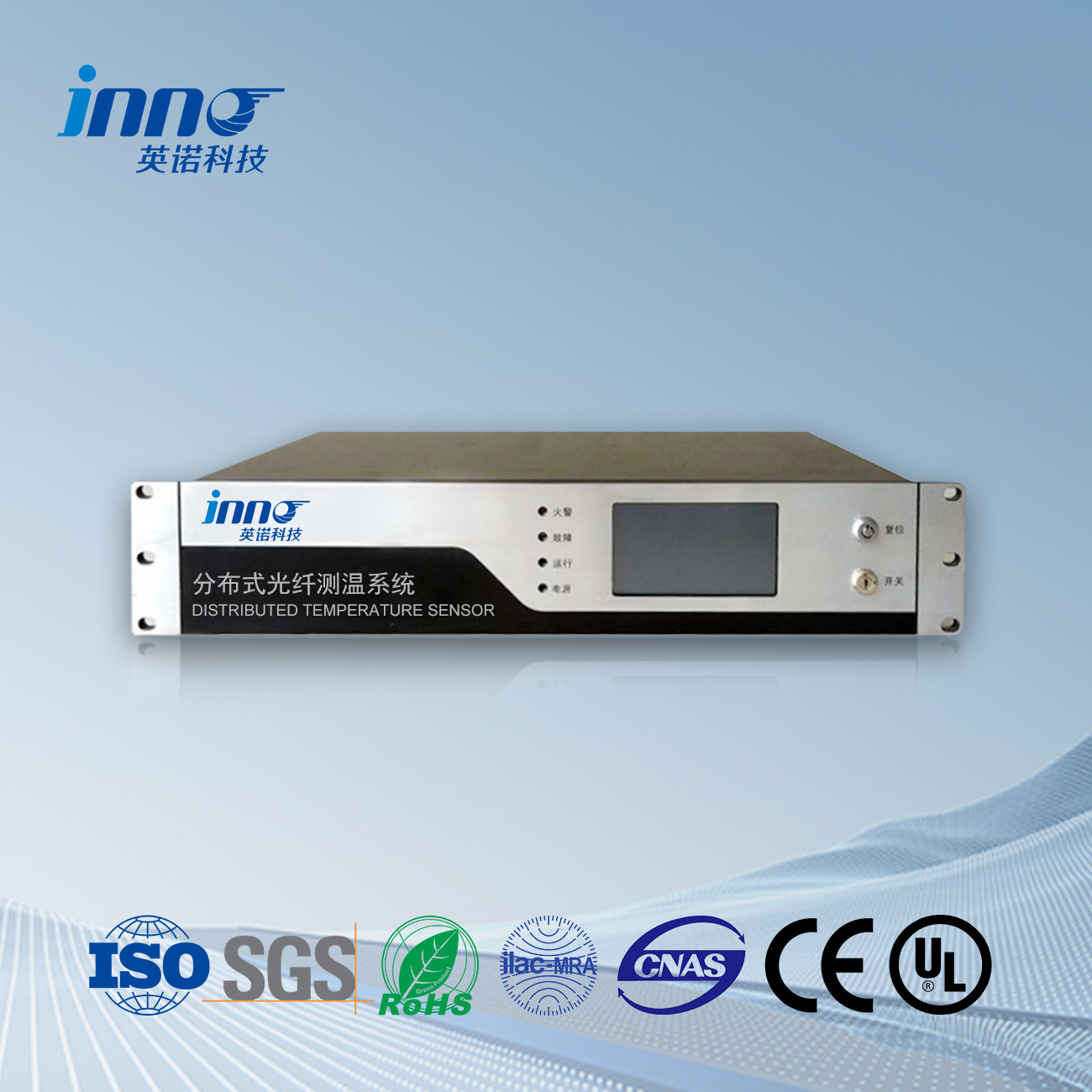
Is this a distributed (DTS) or point sensing system?
It is a point fiber optic temperature sensing system. Each fluorescent probe measures the temperature at a defined location, such as a joint or terminal. This suits IPB monitoring, where the critical positions are known from the design.
How far can the demodulator be from the bus?
Fiber cable length can be configured to the project, and fiber extension cables allow the demodulator to be placed in a suitable control or monitoring area. Provide the required distance when requesting a quotation.
What is the difference between temperature monitoring and protection for an IPB?
Temperature monitoring measures, displays, logs and analyzes temperature data to give early warning of developing hot spots. Protective actions, such as tripping, are handled by the plant’s protection scheme. Alarm outputs from the monitoring system can be used as inputs to the plant control and alarm system, according to the project design.
Can the same system monitor other equipment in the power plant?
Yes. The same fiber optic platform can monitor generator stator and rotor components, transformers, switchgear contacts and busbars. See the generator set and switchgear pages for details.
Learn More About FJINNO Fiber Optic Temperature Solutions
- Fiber Optic Temperature Sensor
- Fiber Optic Temperature Sensor for Busbar and Bolt Connections
- Fiber Optic Temperature Measurement for Switchgear
- Fiber Optic Temperature Measurement System for Generator Sets
- Extension Cable for Fluorescent Fiber Optic Temperature Sensor
- Fluorescent Fiber Optic Temperature Measurement Device
Planning an isolated phase bus temperature monitoring project? Send your IPB drawings or monitoring point list for a customized configuration. Get a Quote or contact us at web@fjinno.net | WhatsApp: +8613599070393
Tags: isolated phase bus, iso-phase bus duct temperature monitoring, generator bus duct, bus duct temperature monitoring, electrical joint temperature, conductor hot spot monitoring, generator transformer connection, GSU transformer, fiber optic temperature sensor, point fiber optic temperature sensing, multi-channel temperature monitoring, FJINNO

Fiber optic temperature sensor, Intelligent monitoring system, Distributed fiber optic manufacturer in China
 |
 |
 |