 INNO fibre optic temperature sensors ,temperature monitoring systems.
- Fiber optic temperature sensors are typically preferred for high-voltage, strong EMI and electrically isolated measurements.
- RTDs are widely used where stable and accurate conventional electrical temperature measurement is required.
- Thermocouples are commonly selected for broad temperature ranges, rugged installations and cost-sensitive applications.
- The best choice depends on electrical environment, temperature range, accuracy, response time, installation and system integration.
Fiber optic sensors, RTDs, and thermocouples are three well-established temperature measurement technologies, each built on a different physical principle. Choosing between them is less about finding a single “best” sensor and more about matching a technology’s characteristics to the electrical environment, installation constraints, and measurement requirements of a specific application. This guide compares all three technologies across their working principles, performance considerations, and typical use cases.
Table of Contents
- 1. What Are Fiber Optic Temperature Sensors, RTDs and Thermocouples?
- 2. How Do These Temperature Sensors Work?
- 3. Fiber Optic vs RTD vs Thermocouple: Key Differences
- 4. EMI Immunity and Electrical Isolation
- 5. Accuracy and Measurement Stability
- 6. Response Time
- 7. Temperature Range
- 8. Installation, Wiring and System Integration
- 9. Fiber Optic vs RTD vs Thermocouple for High-Voltage Equipment
- 10. Which Is Better for Transformer Winding Temperature Monitoring?
- 11. Application-Based Comparison
- 12. Which Temperature Sensor Should You Choose?
- 13. Frequently Asked Questions
- 14. Conclusion
1. What Are Fiber Optic Temperature Sensors, RTDs and Thermocouples?

1.1 Fiber Optic Temperature Sensors
A fiber optic temperature sensor determines temperature by analyzing light transmitted through an optical fiber rather than by measuring an electrical signal. The sensing probe and fiber are electrically passive and non-conductive, which is the defining characteristic that distinguishes this technology from RTDs and thermocouples.
1.2 RTD Temperature Sensors
A resistance temperature detector (RTD) is an electrical sensor whose resistance changes in a predictable, repeatable way as temperature changes. RTDs typically use a metal element, such as platinum, and are widely used across general industrial process control.
1.3 Thermocouples
A thermocouple is an electrical sensor formed from two dissimilar metal wires joined at one end. The junction generates a small voltage that varies with temperature, and this voltage is used to calculate a temperature reading.
2. How Do These Temperature Sensors Work?
2.1 Fiber Optic Temperature Sensor Working Principle
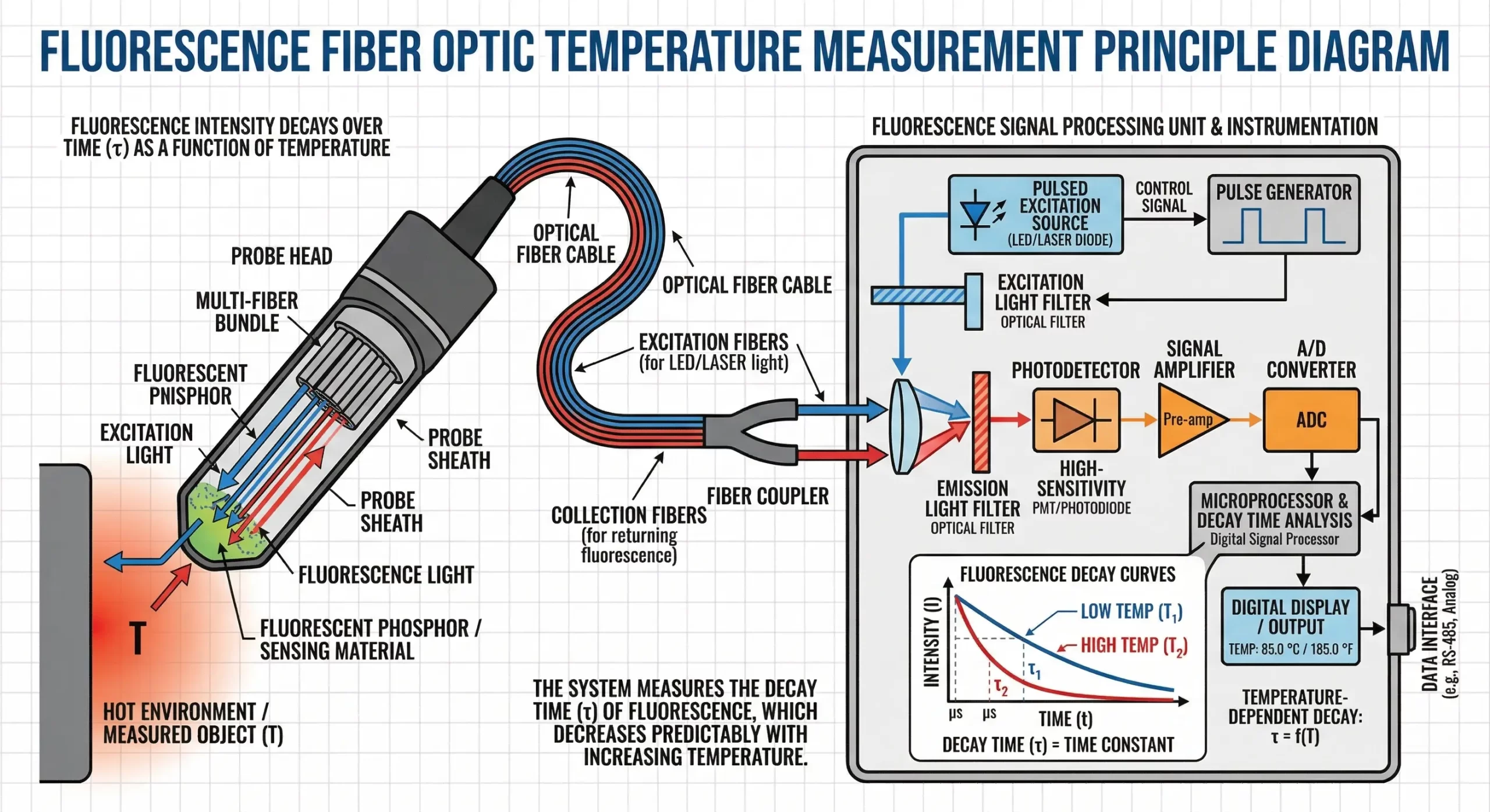
Fluorescence-based fiber optic sensors, the technology INNO focuses on, use a fluorescent sensing material at the probe tip. When excited by light delivered through the fiber, the material emits fluorescence that decays over time. This decay lifetime changes predictably with temperature, and an interrogator measures the lifetime and converts it into a temperature value using a calibration relationship. A full explanation of this and other optical sensing technologies is available in the Fiber Optic Temperature Sensor Working Principle: A Complete Guide, and a deeper look at the decay measurement itself is covered in How Fluorescence Decay Temperature Measurement Works.
2.2 RTD Working Principle
An RTD works because the electrical resistance of its metal element increases in a known, repeatable way as temperature rises. By passing a small current through the element and measuring the resulting resistance, an instrument can calculate the corresponding temperature.
2.3 Thermocouple Working Principle
A thermocouple operates on the Seebeck effect: when two dissimilar metals are joined and the junction is heated, a small voltage is generated across the wires. The magnitude of this voltage correlates with the temperature difference between the measurement junction and a reference point, and this relationship is used to calculate temperature.
3. Fiber Optic vs RTD vs Thermocouple: Key Differences
| Characteristic | Fiber Optic | RTD | Thermocouple |
|---|---|---|---|
| Measurement Principle | Optical (e.g., fluorescence decay lifetime) | Change in electrical resistance | Thermoelectric voltage (Seebeck effect) |
| Electrical Conductivity of Sensing Element | Electrically passive/non-conductive | Conductive | Conductive |
| EMI Immunity | High | Limited without shielding | Limited without shielding |
| Electrical Isolation | Inherent | Requires isolation components | Requires isolation components |
| Accuracy Considerations | Depends on technology, calibration and interrogator | Depends on element grade, wiring and instrumentation | Depends on wire type, junction quality and reference compensation |
| Response Characteristics | Depends on probe design and thermal contact | Depends on element size and sheath design | Depends on junction size and construction |
| Temperature Range Considerations | Depends on probe and material design | Suited to moderate industrial ranges depending on element | Wide range depending on wire type selected |
| Wiring | Optical fiber only | Multi-wire electrical leads | Thermocouple-grade electrical wire |
| Installation | Fiber routing and connector care | Standard electrical installation practices | Standard electrical installation practices |
| Typical Applications | High-voltage equipment, strong EMI environments | General industrial process control | Wide-range industrial processes, rugged environments |
| High-Voltage Suitability | Well suited due to passive, non-conductive probe | Requires additional isolation measures | Requires additional isolation measures |
4. EMI Immunity and Electrical Isolation
Fiber optic sensing transmits temperature information as light through a dielectric fiber, so the sensing point carries no electrical current and is not affected by nearby electromagnetic or radio-frequency fields.
RTD electrical wiring, by contrast, is conductive and can pick up induced currents or noise when routed near strong electric or magnetic fields, unless properly shielded and grounded. Thermocouple electrical wiring faces similar considerations, since the thermoelectric voltage signal is small and can be susceptible to interference from nearby EMI sources if not adequately shielded.
In equipment that generates strong electric and magnetic fields — such as transformers, generators, and switchgear — this is why optical sensing is useful in high-voltage equipment: it avoids introducing a conductive path or an EMI-susceptible signal at the measurement point.
5. Accuracy and Measurement Stability
No single technology can be called the most accurate in all cases. Accuracy depends on several factors that apply across all three sensor types:
- The specific sensor type and grade
- Calibration quality and traceability
- The temperature range being measured
- The instrumentation used to interpret the sensor signal
- Installation quality, including thermal contact and probe placement
- Wiring or fiber routing practices
- The surrounding environmental conditions
Because these factors vary widely by application and product, accuracy specifications should always be verified against the datasheet of the specific sensor and instrument being considered.
6. Response Time
Response time for all three technologies depends primarily on the physical construction of the sensing element and how well it is thermally coupled to the object being measured, rather than on the sensing principle alone. Smaller, more directly embedded sensing elements generally respond faster than larger or more thermally isolated ones, regardless of whether the underlying technology is optical, resistive, or thermoelectric. Specific response time figures vary by product and should be confirmed against the relevant datasheet rather than assumed from the sensing technology alone.
7. Temperature Range
The usable temperature range for any of these three sensor types is determined by the specific materials and construction used, not by the sensing principle in general. RTD elements, thermocouple wire types, and fiber optic probe materials are each available in different grades and designs intended for different temperature ranges. Because of this variation, this guide does not state absolute temperature range figures for any technology; range should be confirmed against the datasheet of the specific product under consideration.
8. Installation, Wiring and System Integration
8.1 Fiber Optic Sensor Installation
Installation involves placing the fiber optic temperature probe at the measurement point and routing the optical fiber back to the interrogator, with attention to bend radius and connector cleanliness to preserve signal quality.
8.2 RTD Wiring
RTDs are connected using standard electrical wiring configurations (commonly 2-wire, 3-wire, or 4-wire), with wiring choice affecting how lead resistance is compensated for in the measurement.
8.3 Thermocouple Wiring
Thermocouples require thermocouple-grade wire matched to the specific thermocouple type, along with proper reference junction handling to maintain measurement accuracy.
8.4 PLC and SCADA Integration
All three sensor types can typically be integrated into industrial control systems, though the specific interface depends on the instrument used. Fiber optic interrogators may offer outputs such as RS485, Modbus, analog signals, or relay outputs depending on model and configuration, while RTD and thermocouple transmitters commonly use standard analog or digital industrial protocols. Exact interface support should always be confirmed against the corresponding product datasheet.
9. Fiber Optic vs RTD vs Thermocouple for High-Voltage Equipment
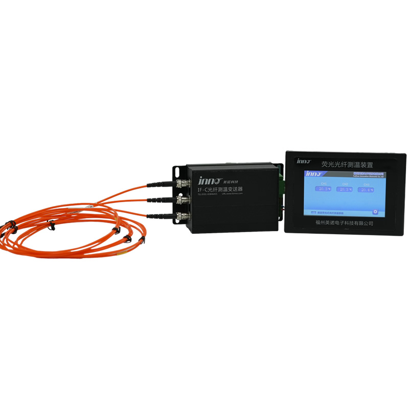
Transformers, generators, reactors, switchgear, and high-voltage test systems all involve elevated voltages and, in many cases, strong electric or magnetic fields near the measurement point. In these settings, a sensing element that is electrically passive can be placed closer to live components without introducing a conductive path back to grounded instrumentation.
RTDs and thermocouples remain in wide use in high-voltage equipment as well, particularly at measurement points that are further from the strongest fields or where additional isolation and shielding can be practically applied, such as certain oil temperature or ambient monitoring points.
10. Which Is Better for Transformer Winding Temperature Monitoring?
Transformer winding hot spots occur deep within the winding structure, an area subject to high voltage potential and significant electromagnetic activity. Fluorescence-based fiber optic probes are commonly embedded directly between winding layers, providing direct temperature measurement at the hot-spot location while remaining electrically isolated from grounded instrumentation and immune to the surrounding EMI. This makes fiber optic sensing well suited to transformer winding temperature monitoring at the hot-spot itself.
RTDs and thermocouples continue to have established roles elsewhere in transformer temperature measurement, such as monitoring oil temperature or ambient conditions at points where direct electrical connection to grounded instrumentation is more practical.
11. Application-Based Comparison
| Application | Typical Technology to Consider |
|---|---|
| Transformer winding hot spot | Fiber optic sensing is a typical choice due to electrical isolation and direct embedding |
| Transformer oil temperature | RTD or thermocouple is commonly considered, depending on installation point |
| Generator winding | Fiber optic sensing may be suitable where EMI immunity and isolation are priorities |
| General industrial machinery | RTD is commonly considered for stable process monitoring |
| High-temperature process | Thermocouple is commonly considered for broad temperature range needs |
| Strong EMI environment | Fiber optic sensing is a typical choice due to inherent immunity |
| Laboratory measurement | RTD or thermocouple may be suitable depending on required range and setup |
| Power electronics | Fiber optic sensing may be suitable where isolation from switching noise is needed |
12. Which Temperature Sensor Should You Choose?
12.1 Choose Fiber Optic Temperature Sensing When…
- The measurement point is at high voltage potential or within a strong electromagnetic field
- Electrical isolation between the sensing point and instrumentation is required
- The probe must be embedded directly within equipment such as a transformer or generator winding
12.2 Choose an RTD When…
- Stable, well-characterized electrical temperature measurement is needed in a conventional industrial setting
- The measurement point is not subject to significant EMI or high-voltage exposure
- Standard electrical wiring and instrumentation are practical to install
12.3 Choose a Thermocouple When…
- A broad temperature range must be covered
- The application involves rugged installation conditions
- Cost-sensitive, widely available electrical sensing is preferred and EMI exposure is manageable
13. Frequently Asked Questions
Is a fiber optic temperature sensor more accurate than an RTD?
Accuracy for both technologies depends on the specific product, calibration, and installation quality, so neither can be called universally more accurate without reference to a specific application and datasheet.
What is the main difference between RTD and thermocouple?
An RTD measures temperature through a change in electrical resistance, while a thermocouple measures temperature through a small thermoelectric voltage generated at the junction of two dissimilar metals.
Which sensor is best for strong electromagnetic fields?
Fiber optic sensors are generally preferred in strong electromagnetic environments because the sensing element and fiber are electrically passive and not affected by induced currents or interference.
Can RTDs be used inside transformer windings?
RTDs can be used in some transformer temperature measurement points, but their conductive wiring requires careful isolation when placed at locations subject to high voltage or strong EMI, such as directly within winding hot spots.
Why use fiber optic sensors in high-voltage equipment?
Fiber optic sensors use a non-conductive probe and fiber, which allows temperature measurement directly at or near high-voltage components without introducing an electrical connection to grounded instrumentation.
Are thermocouples affected by EMI?
Thermocouple signals are small voltages carried on conductive wire, which can be susceptible to electromagnetic interference if not properly shielded, particularly near strong EMI sources.
Which temperature sensor is best for transformer winding hot spots?
Fluorescence-based fiber optic probes are commonly used for direct winding hot-spot measurement because they can be embedded within the winding while remaining electrically isolated and immune to EMI.
Does a fiber optic temperature sensor require electrical wiring at the sensing point?
No. The sensing probe and the fiber connecting it to the interrogator carry only light, not electrical current.
Which sensor has the fastest response?
Response time depends mainly on the physical construction of the sensing element and its thermal contact with the measured object, rather than on the underlying sensing principle, so no single technology can be called universally fastest.
Can fiber optic sensors connect to PLC or SCADA systems?
Many fiber optic interrogators support industrial communication interfaces such as RS485, Modbus, analog, or relay outputs, depending on the specific model and configuration; exact support should be confirmed against the datasheet.
14. Conclusion
Fiber optic, RTD, and thermocouple temperature sensors each serve a distinct role in industrial temperature measurement. Fiber optic sensing is best suited to electrically isolated, EMI-intensive, and high-voltage point measurements, such as direct temperature monitoring within transformer or generator windings. RTDs remain a strong choice for conventional industrial temperature measurement where stable, well-characterized electrical sensing is practical. Thermocouples are widely used for broad temperature ranges and rugged industrial applications where a simple, cost-effective electrical sensor is appropriate. Selecting the right technology depends on matching these characteristics to the specific electrical environment and measurement requirements of the application.
Related Resources
- Fiber Optic Temperature Sensor Working Principle: A Complete Guide
- Fluorescence vs FBG Fiber Optic Temperature Sensors
- Fiber Optic Temperature Probe
- Transformer Fiber Optic Temperature Monitoring
- High-Voltage Equipment Temperature Monitoring
- Motors and Generators Temperature Monitoring

Fiber optic temperature sensor, Intelligent monitoring system, Distributed fiber optic manufacturer in China
 |
 |
 |